github link:
The codes for the Project can be found in our Github that is linked under.
https://github.com/Shallow-Blue/AutoChess
Sondre Fuhre Orsten and Ole Henrik Eidal Flesaker:
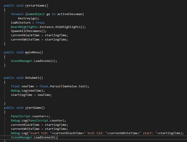
This final week we have been trying to clean up code, add features to make the game complete and implementing an UI. The features to make the game complete that have been tried, but we did not manage to make work: Castling (“swapping” place with king and rook, given some conditions). And not being able to put your own king in check.
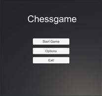
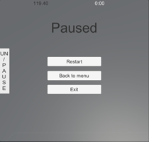
The UI now has a menu screen, pause button and screen, victory screen and options screen. Menu consists of 3 buttons: Start game, options and exit. Options brings you to the options screen, where you can set a time control for the game, which we sadly did not manage to make work. Exit is attached to a “quit application” script that works if the game is made into and application, does not really serve a function at this time. When you hit the play for the game, the timer for white starts, as it is whites turn. It will continue to count down until white makes a move, so its blacks turn, and black’s timer counts down. If either sides timer runs out it will make them lose. On the game screen there is a pause button that pauses the timer and takes you to the pause screen. Pause screen shows the timer for both teams, it has a reset button that resets the game, a back to menu button and a non-functioning exit button.
Now all communication back and forth between our Arduino program and our Unity program is finished implementing. There are also some features that have been put on hold as everything have not been ready to test. The physical board and therefore the camera detection.


Helge Sondre Ulberg, Oriana Presacan.
The main script for camera can be found in the Github above or directly to the subfolder down below.
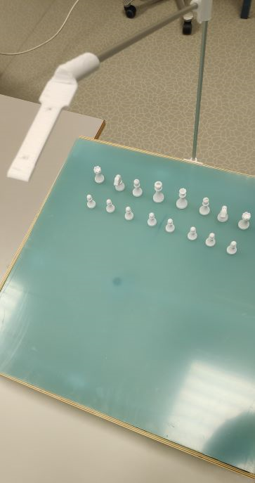
We have been working on the classification of the pieces during the last week. The T-Shape algorithm we implemented was not as precise as we needed it to be, so we didn’t have enough data to differentiate between pieces.
Therefore we came up with another approach: we divided the 640×480 pixels into 64 squares. 160 pixels (80 pixels on each side of the length) will not be used, so to have only 60×60 pixel squares. While the program is going through all the pixels of each square (row 1 column 1, row 1 column 2, and so on), it is generating the average and the maximum height, and counting the total number of pixels. These 3 values help us classify the pieces. We have also included some helping lines to make the squares easier to visualize. Every time a piece is identified, a white square with the name of the piece will appear over it.
The algorithm works as expected, but the only problem is that the values of the pieces change every time we put up the camera since we don’t have the board nor the stand to know the exact position of the camera. Another thing we noticed is that the values of the same piece are different in every square (probably because of the angles), so we would have to measure each piece in 64 different locations to make our program work really accurately. Since the board isn’t finished yet, doing that now would be useless.
Hence, to prove our work, we measured the values of the pieces for the first 3 columns and then made a video. So the final version of the code has all the values for 3 columns. If we have the board by Friday, we will try to measure everything again and present it.
Another idea would be to print the maximum height, average height and total number of pixels only once every 10 rounds. So the program will read all the pixels as explained above, and will make an “average” for 10 rounds for each of the 3 values. This way we hope the values will be more accurate.

Osmar Ferreira de Freitas
During the last weeks, the code for the hardware module, including the motor control was worked on. The implementation had to suffer a refactoring due to the way that the project needed to be made, in this case, through unity, so according to the UI implementation, some of the commands needed to be changed. Some tests with the code in the arduino with the board allow some correction in the circuit, and the board itself, even though it’s not perfect, it proven to be working.
Stian Bergstrøm:
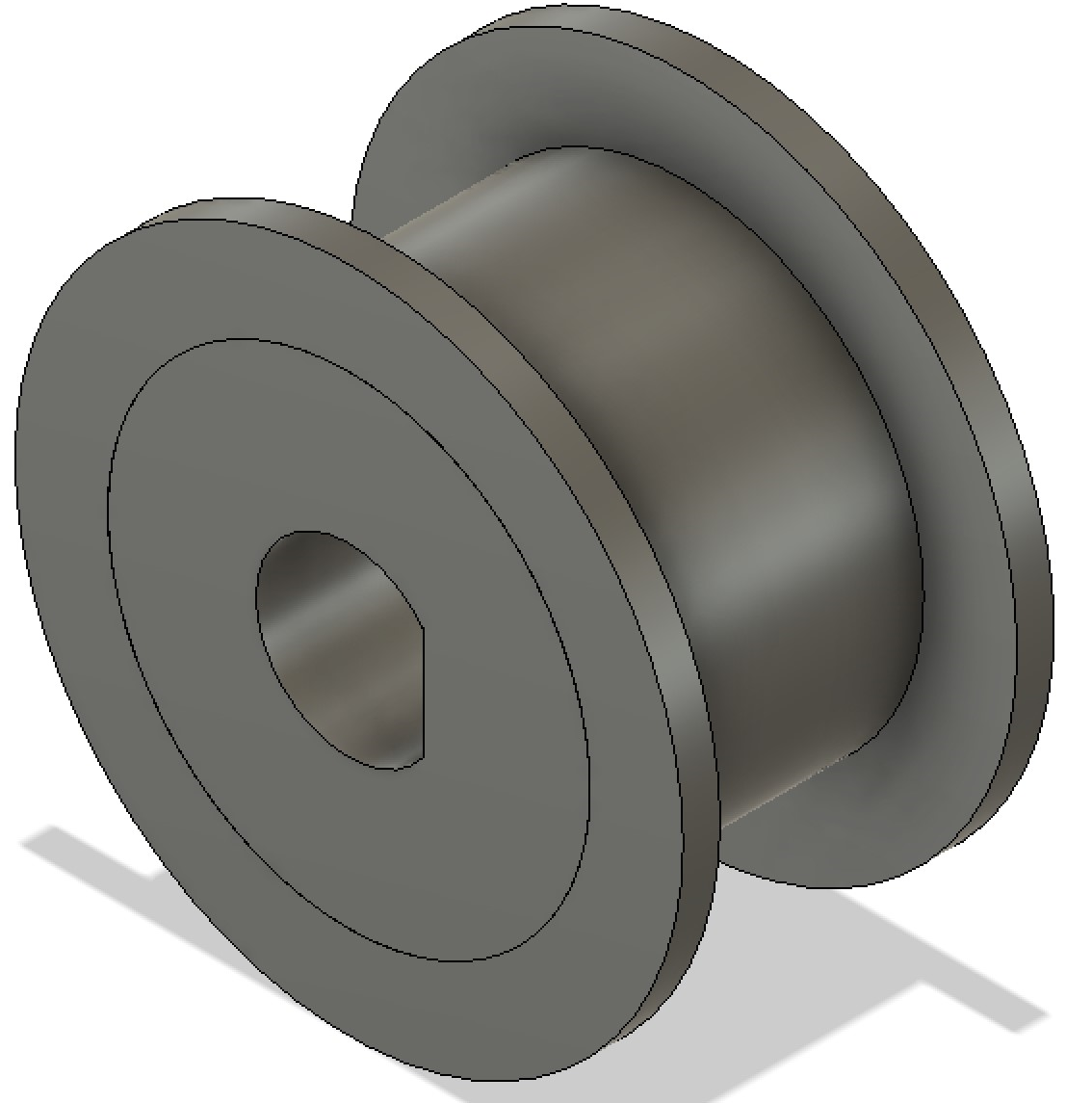
For the last week I tried to finish the board so we could connect the basic components and get a basic function. I had to sand down all the 3D printed pieces that was going to be mounted around the aluminium rod. The pieces was way too tight to be able to move along the tube. with all the parts sanded down and connected to the rods agian It was able to slide but it is not optimal. It would have been better to apply a metal tube that is slightly bigger than the 8mm rod and mount the 3d printed slider on top off that to remove some friction. When I was applying the string for the motion I found that the string that was bought was not strong enough. Had to try a thicker string that worked, but the pulleys should then have had a bigger edge so that it is less likely to slip off.
When I was going to mount the motors I found that there was a design flaw in the board. There was not enough height on the board. When the design was made I had forgot to add the height of the electromagnet and the height for the plexiglass and bottom thickness. The plexiglass then may need to be mounted on the top instead to be placed on the inside of the side planes. For the motor the string did not work as intended. We should have used a gt2 belt between the motors and the rods and then could have used string between the parallel rods to the sliders. Instead of string I ended up trying to use rubber bands. That is not the best solution, but didn’t have any time left to make new parts. The pulleys that are attached to the motors and that are attached on the rods for the motors does not have a wide enough edges. When the motor had been running for a little while the rubber bands started to slip of and had to be moved back in place so it was enough tension to get the movement from the motor to the rods.
The camera stand have also been applied to the board. It is connected to the board only by fitting the rod in the holder and is not screwed in place. For easy storage it is easy to place and take off. It is a little flimsy with only one rod for between each printed pieces. If we had more iteration it should be a little sturdier for better accuracy with the camera.
For the electric I was able to connect the motors and the stepper driver to the Arduino. I used a simple Arduino code to test that the motors was able to move the axis system.
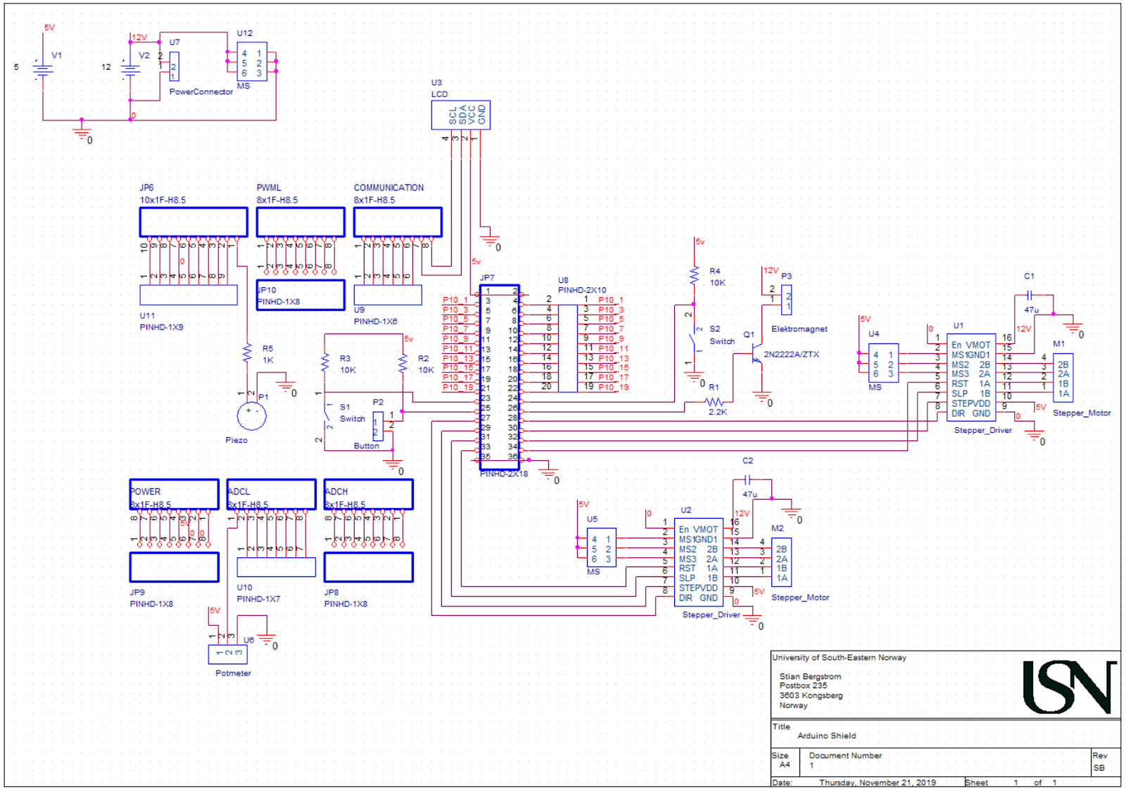
Since the PCB did not arrive in time we had to mount all our electronics to breadboards. Had an issue with one stepper driver, but it turned out that the bread board did not function. For our basic function we need the motors, endstop and electromagnet. We are missing the transistor for the electromagnet so we can control it with the Arduino. The circuit is needed since the electromagnet is controlled with 12V and the Arduino can only output 5V.
For the schematic I have updated some of the values for the components. The schematic is for the PCB so there is features that is connected on the schematic that is not part of our system at this moment. In the schematic JP6, PWML, Communication, JP7, power, ADCL and ADCH are the arduino pins.