Helge Sondre Ulberg, Oriana Presacan
This week we were trying to make a new data type for our program. With this new data type we will hopefully be able to see the height and colors of the pieces. This will give us more possibilities to differentiate between pieces and more accurately detect witch pieces we can see with the camera.

Sondre og Ole Henrik
This week we continued on finding a way for unity to communicate with arduino. We started off with different guides and tutorials, with no success. Then we imported an asset called ardity and were able to send simple signals to turn on different lights on the arduino.
Osmar:
This week the focus was on the development of the Arduino interface with the other components of the system. The trace function was developed using serial communication, specifying the initial point, and the final point. The LCD screen implementation has started also. Other functions were also implemented, as recalibration, and serial communication testing. I had the opportunity to talk to the group responsible for implementing the manager of the system to let them know what are the inputs and outputs of the Arduino module, and to gather information about what they are working on.
Stian Bergstrøm:
The most important components for our system are the motion and electromagnet. The LCD screen is to have a menu where you can start the game and chose the settings. With the potentiometer and button to control the menu. With the piezo speaker we can add a little bit of feedback to the player on certain moves.
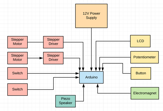
Stepper motor:
For the motion of the system we need the motors to be able to have a positional accuracy. For this task we could use a DC motor with an encoder or a stepper motor. We have chosen to use stepper motors. The reason we are going to use stepper motors is that with a stepper driver they can be easily programmed to move a certain steps. Our stepper motor is a 1.8° per step. That means for one rotation it needs to go 200 steps. With this in mind we know that it would be suitable for our sysem with a stepper driver to controll it.
Stepper Driver:
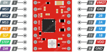
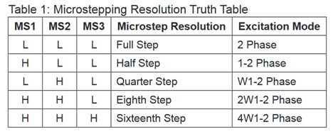
The stepper driver that we are using is the A4988. The A4988 is a simple and cheap stepper driver. The stepper driver is a This stepper driver is connected to the Arduino with a step and direction. With the step pin you can declare the speed of the motor and the direction is the direction it rotates. This stepper driver can be run in full step to sixteenth step as seen in the figure below. With microstepping you can split up the stepping resolution to get a more smooth motion and higher precision. With the driver you can choose the microstepping resolution with the MS1-3 inputs as seen in the tablebellow.
For our purpose the A4988 stepper driver is good enough. The driver can give out 2A current and you can connect up to 35V to the supply voltage. This is more than enough since our motors is rated to 1.5A.
This stepper driver does not have any sensor to be able to detect the current in the stepper motor. The current for the motor is controlled by a potentiometer on the board. Because of this we can’t use the stepper driver to detect if our x axis is running into the end of the axis. We then need to use switches to be able to home the motors. The switches need to be mounted to the end of the railing so that the axis can drive into it. The reason we need this is to be able to declare where x=0 and y=0 is on the axis system.
PCB:
Continued the work on the PCB for the system. Since it is going to be an arduino shild I retrieved the design for the arduino. With this design I was able to retrieve the schematic and board design for the arduino to work from and add ou components. I have been able to start working on the routing of the board, but forgot to add a controll circuit for the elektromagnet to be able to controll it. So I need to go back and add this to the schematic.