The group has agreed on meeting once a week, on Thursdays. This update summarizes the last week of work and progress. As of right now there are 3 main problems, creating the hardware for the car, research into software solutions, and the design and prototype of a grab mechanism.
Hardware
The Arduino pre-mounted on the vehicle was a good starting point for us to understand how the motors work, so at the start of the week we programmed a small library for controlling the car. But the Arduino has its limitations, it has very limiting computing power and is not sufficient for our machine learning based 3D-mapping software. Therefore we have decided to switch out the Arduino with a Raspberry PI.
We have also started modifying the car, making sure all the wires were properly connected and that it could function with an external power supply. We also removed components that was not needed for our functionality, and in total we removed the light and the distance sensors.
The Raspberry PI can mimic all functionalities that the Arduino provided with its 26 GPIO-pins. It will also be programmed in C so the code will not be too different and should be easy to port. We started the work of migrating to the Raspberry PI this week but did not finish it.
In the next week our goal is to finish the migration to the Raspberry PI and have the basic functionalities of the car working, that is if the group members assigned to 3D-mapping manage to get it up and running. We’re planning on having the 3D-mapping software work on the Raspberry PI with inputs from a mobile phone outputting sensor data such as camera and IMU.
Main components used in car:
- Arduino
- Raspberry PI
- 2x 6V DC Motors
- Arduino DC Motors L298N Controller
- 9V Battery

3D-Mapping
After some research into 3D-mapping and how we found ROS, which stands for Robot Operating System and is an open-source meta operating system for robots. Though it is not an operating system it is a robotics middleware that provides services that you would expect from an operating system.
There is multiple open-source 3D-mapping software made and published to be used with ROS. Two solutions for 3D-mapping we’ve looked more into for ROS are VINS-MONO, a mapping software using only a single camera and an IMU, and RTAB-Map which uses a stereo camera and the movement of the controlled object to determine the surroundings. Sadly due to lack of experience with both Linux operating systems, ROS, and the software we’re attempting to try out, these solutions have taken longer time than expected to get to work for trying out, and we’re hoping to get these running within the week.
Arm/Grip Planning
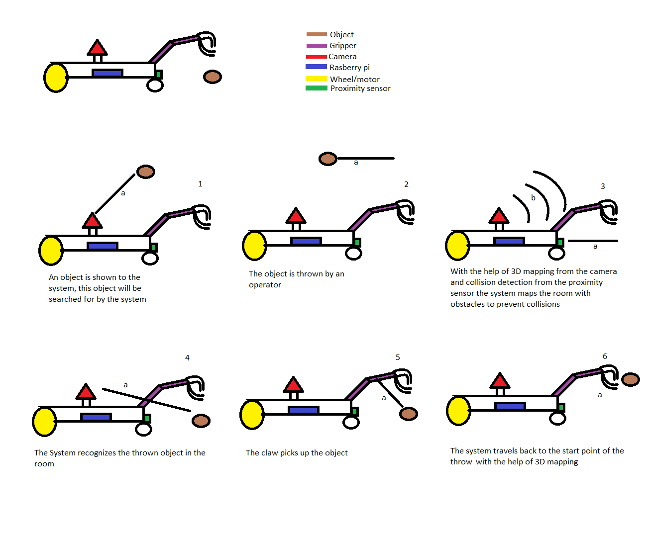
One of the requirements for our system is for it to be able to pick up an object that has been thrown before returning it. This means we’re going to need some form of arm to grab the object and hold it, until the car/drone has returned to it’s starting position. The arm or grabbing mechanism will therefore either have to contain the object with it’s arms, or grab it before lifting it back. It is important to have the function area of the arm outside the frame of the camera, mainly because the car/drone will have to recognize the object using vision.
The arm needs a signal-based function. This can be an arm that has two states, ON and OFF. Condition “OFF” is that the arm does not hold the object and state “ON” is that it holds the object. Then it can be a robotic arm that has joints to hold the object in the air.
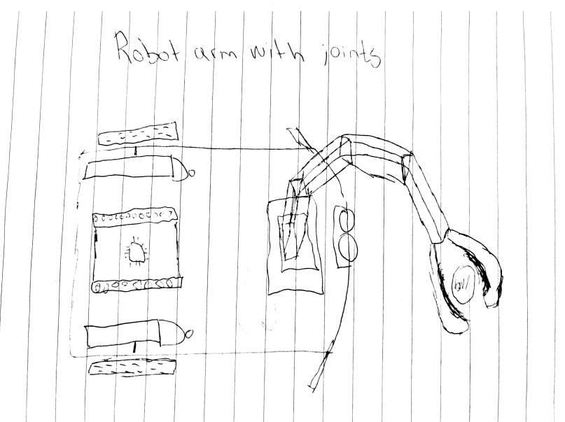
Fig. 1 is based on a robot arm that is advanced and has multiple joints. Less relevant to our task since the object is going to move with the car/drone. The reason why this is considered is that it holds the object in the air, then it doesn’t get in the way of the camera nor the wheels.
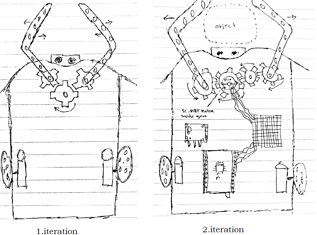
This arm should be attached to the car as shown here in fig 2. second iteration. It’s going to have two states that will perform the task of holding the object during the process. Our next task will be to conclude which we are going to use and start to build a prototype of the arm to test it.