Hello Wørld!
The last official week of the MiniMuck project consisted of merging, integration, launch scripts, testing, filming and reflections on the decisions made and what the project became.
Summary of the Project
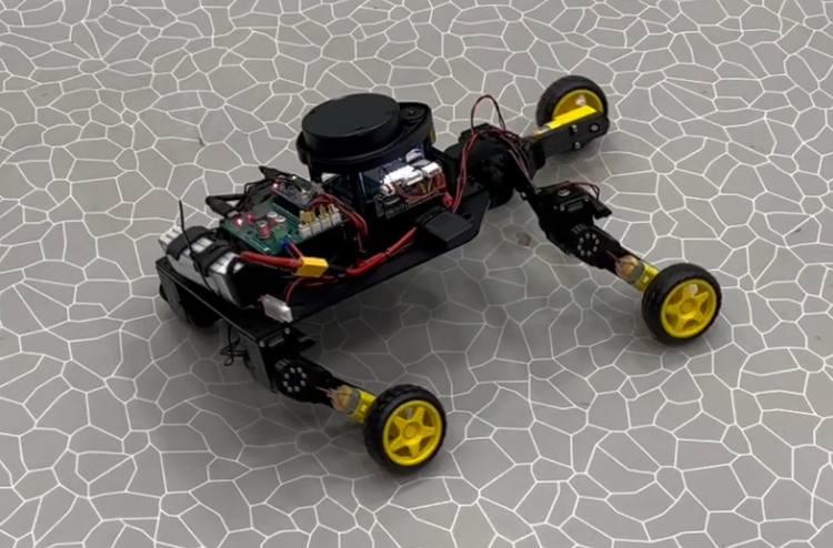
To summarize the project, we have designed and developed a mechanical, electrical and software-based system for driving through terrain while mapping with LIDAR. We have focused on getting an insight into applicable technology for the bachelor thesis, and this has been an important aspect in many of the design choices.
The hardware and software are based around the following technologies:
- Raspberry Pi 5 computer for higher level software controlling the robot and processing LIDAR data with RPI Sense Hat for pressure, humidity, temperature, color, orientation, and movement sensor capabilities.
- OpenCM 9.04 Microcontroller for controlling the motors and servos by instructions from the RPI through UART
- Dynamixel XM servos with a built-in microcontroller for controlling the individual servos in a more advanced manner than regular hobby servos
- Neato XV-11 LIDAR driven from a custom-made PCB enabling direct PWM speed control from the RPI, and UART feedthrough
- Custom made Switch Mode Power Supply and Motor Control PCB for controlling brushed DC motors using the OpenCM, and powering the Raspberry Pi over USB-C. Here, a room for improvement is that the power supply should incorporate a USB Power Delivery IC to negotiate 5V-5A power supply to avoid the RPI throttling down.
Early on, we decided to control the motors and servos using a separate microcontroller. We could have used expansion boards for the RPI, but by having a programmable platform with only a few specific tasks, we were able to test the hardware separately without having to implement all the functions before being able to test anything, which was a major advantage, however it introduced complexity in the final implementation.
The project has not been smooth sailing, even humbling at times, hence we have learned a lot in PCB design with custom footprints and symbols, designing for USB power delivery, Driving brushed DC motors with H-bridges, mechanical design of a drivable vehicle, developing with the ROS2 framework using ROS2 Jazzy Jalisco, ROS2 Control and Rviz while focusing on making modular and scalable software and hardware while testing continuously on the hardware.
https://gitlab.com/mini-muck/mm_software_2025
Collectively
This we worked mostly together, which was natural since we integrated all parts of the project together. We started by merging the different git branches together. The modularity of our code made the merging process very smooth. After the integration we made a launch script for the lidar/slam code. So that the process of starting the MiniMuck is just to launch two scripts. This was also the point where we disassembled the MVP vehicle, and assembled the final hardware fully by integrating the LIDAR and Raspberry Pi 5 onto the final vehicle.

Testing
After the integration we started testing the whole system. We needed to test these things:
- Startup sequence of electrical system
- Legs with different ride heights
- Demo script for legs
- Driving with different ride heights
- LIDAR
- Mapping with LIDAR
- Wireless Driving
Legs and Driving
Starting off with the legs we started with passing different values to get different leg configurations. We mainly tried seven different configurations as pictured on the right.
While testing, we discovered that the lower ride configurations work better with the on-the-spot diff drive turning. This comes from the CoG being shifted further back so that the back wheels have more friction and the front wheels have less. We also tested changing the leg configuration while driving. This worked well as seen in the test videos.

We had to make some small adjustments to the lowest ride height (low rider mode). We did this to avoid hitting the ground with the rear end of the MiniMuck. The cause for the issue was flexing of the mechanical structure. After raising the rear legs a bit, the MiniMuck can now drive with all 7 shown configurations without any issues.
LiDAR and Mapping with The LiDAR
The LiDAR also worked as intended sending the LiDAR data to the slamToolBox for mapping. The mapping did not work as expected during the test. While driving we saw that the mapping got noisy fast. The reason being a mismatch with the speed slamToolBox thinks the MiniMuck is driving and turning, and how fast it is driving and turning in real life. We found that the turning was the main issue and causing the most noise. This is a point of improvement that could be looked at in the future.
Wireless Driving
We also tested driving wirelessly connecting the battery up and using ssh to connect to the Raspberry Pi to start the scripts remotely. We did not get the keyboard input to work over ssh, so we had to connect the keyboard to the RPI with Bluetooth to get it driving. We also had some problems with getting the different Links between the different transform frames to work over ssh. This was fixed by hard coding a child frame id.
But after some fixes and solutions we had the Mini Muck able to drive around the room wirelessly and having the ability to start the scripts remotely using ssh.
Leon
Since my technical work for the project was mostly tested and finished last week, I worked on the integration and testing of the system this week as well as some organizing and writing READMEs. The only individual work I did was a demo script for the legs to move in a set pattern for the demo.
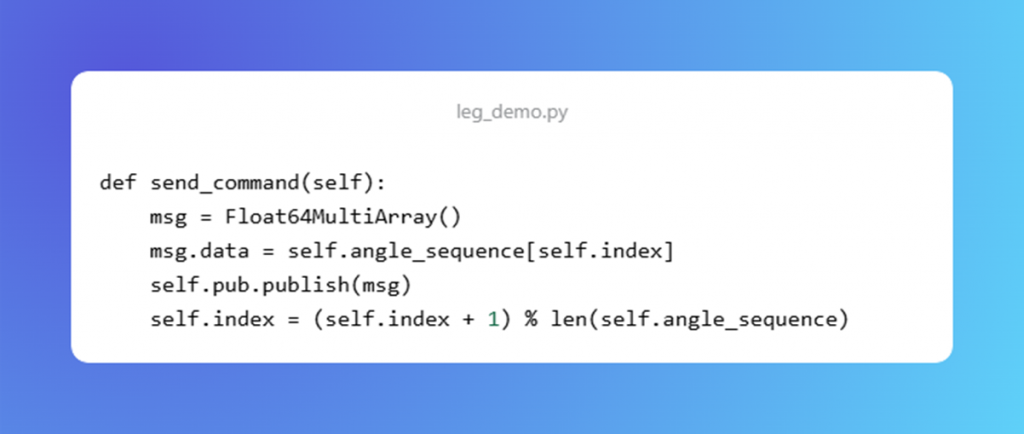
The leg_demo.py script consists of a given pattern for the legs to move to showcase some of the possible positions. Here is the function that publishes commands to the position controller.
https://gitlab.com/mini-muck/mm_software_2025/-/tree/control_branch?ref_type=heads
Herman
This is the final weeks of the project. Since my technical work was finished last week, I was working with the group on the final assembly, testing, and debugging of the system. I have also worked on summarising the project and sorted all documents and files I made during the project, while updating the schematics and PCB layout with the final changes made along the way. The document below is a collection of most of the schematics, pcb layout, reports, power budget, BOM and interface control document.
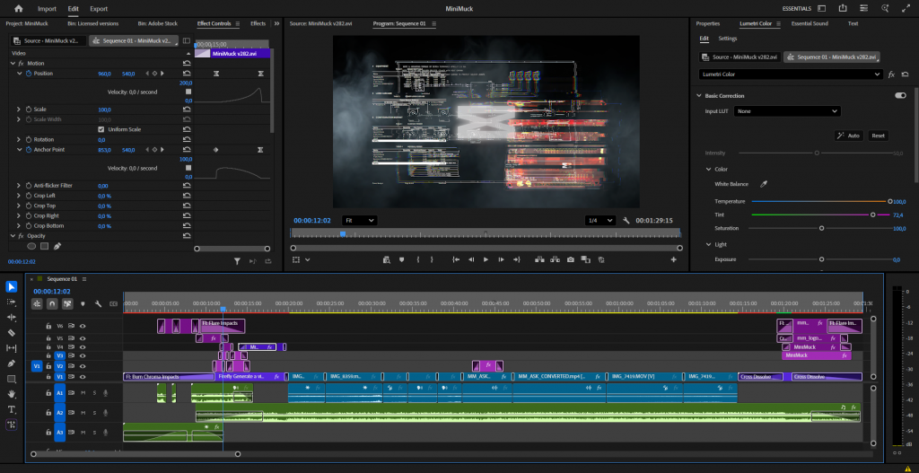
Finally, I produced the demo video with royalty free audio and some special effects highlighting some of the electrical, mechanical and software aspects of our project.

Ask
Hei Bloggen for the last time!
This was the last work week on the mini muck project, so this week have gone to testing the mini muck for the most part written about in collective part of the blog.
Small fixes
Other than testing this week has gone to fixing small config settings for the raspberry pi turning on Bluetooth and enabling the possibility for ssh.
Starting all the scripts from ssh gave an new error we didn’t have when running the scripts from the pi.
Error Message:
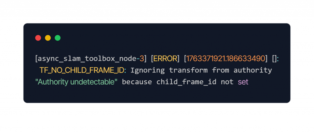
The fix for this was to add a child_frame_id to the odomToTF script. This fixed the problem.
Results from the LiDAR mapping
From the videos seeing the lidar mapping we see that it gets noisy quite fast and not that accurate. This is because the speed the mini muck is driving and turning is a mismatch with the speed the slamtoolbox think the mini muck is driving and turning. This is a point of improvement that could be looked at in the future. The only way to do this at this point is to take educated guesses to sync this up. This has not been the biggest priority in the last stint therefore not been done.
The project is finally complete, and we can look back on a lot of learning through failing and especially on how to adapt through unforeseen and challenging situations. We are proud to present a working prototype using technologies completely new to the group. Through working outside of our respective disciplines, we have gained new perspectives and knowledge, while becoming aware of our capabilities and shortcomings.
Thank you, and off you go MiniMuck!