Hello Wørld!
This week the team has tested the robotics and LIDAR, and resolved the remaining problems. We now have all systems working individually, and a complete integration is closer than ever. At this pace MiniMuck is expected to arrive next week!
Leon
Testing:
This week started with more testing. After some tweaking rqt finally found the controller manager and the leg controller. The testing then showed that the MiniMuck recived the command, moreover the servo was twitching, instead of going to the desired position.
Through the debugging to fix the twitching, I found a few faults in my hardware interface code that when fixed made the MiniMuck turn when driving, and not just when static.
When testing we got an overrun error. The error stated that a run through of the code took too long, which is leading to problems. The main issue was reading time which led to Herman finding some hanging writes from early debugging in the motor controller code. This proved to be the reason for the error.
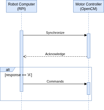
Moving on, we set up a handshake in the startup of the communication between the robot computer and motor controller to make sure that we don’t get any offset in the messages because of the motor controller not being able to read packages fast enough. We did this to try to fix the twitching of the legs, however it didn’t fix the issue.
Debugging step by step:
Since we still hadn’t fixed the leg servo problem, we went back to basics. We tested each part separately to isolate the problem. First, we checked that everything on the motor controller worked. It did. We then checked that communication worked, and after testing the new handshake we were confident in the communication. The startup of the servos at 180 degrees (NULL position for the legs), also worked, which means that commands from the Hardware interface worked.
The only part left then was rqt. And after a after a while finally understood that the way we are dealing with the movement of the legs are position based, while the controller is trajectory based. This led to the twitching problem. We then switched to the JointGroupPositionController. And tried to use rqt with it, but rqt doesn’t work with position_controllers. At last we tested with commands in the command line, and controlling the legs finally works!
https://control.ros.org/jazzy/doc/ros2_controllers/position_controllers/doc/userdoc.html
Moving on, in the last reqular week of the project, the plan is to make a python script to control the legs, and merge the control and lidar code to finalize the MiniMuck project!
https://gitlab.com/mini-muck/mm_software_2025/-/tree/control_branch?ref_type=heads
Herman
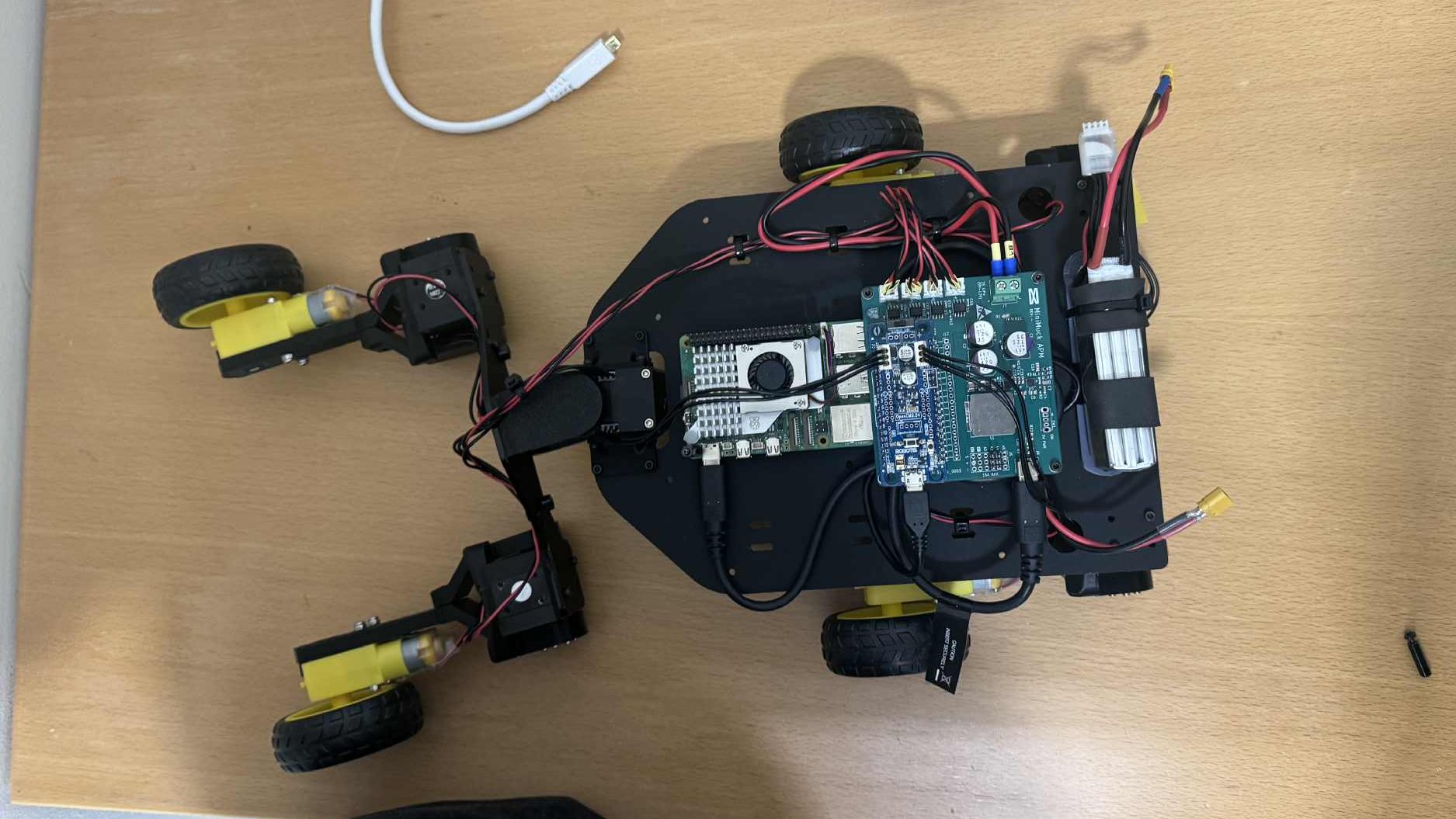
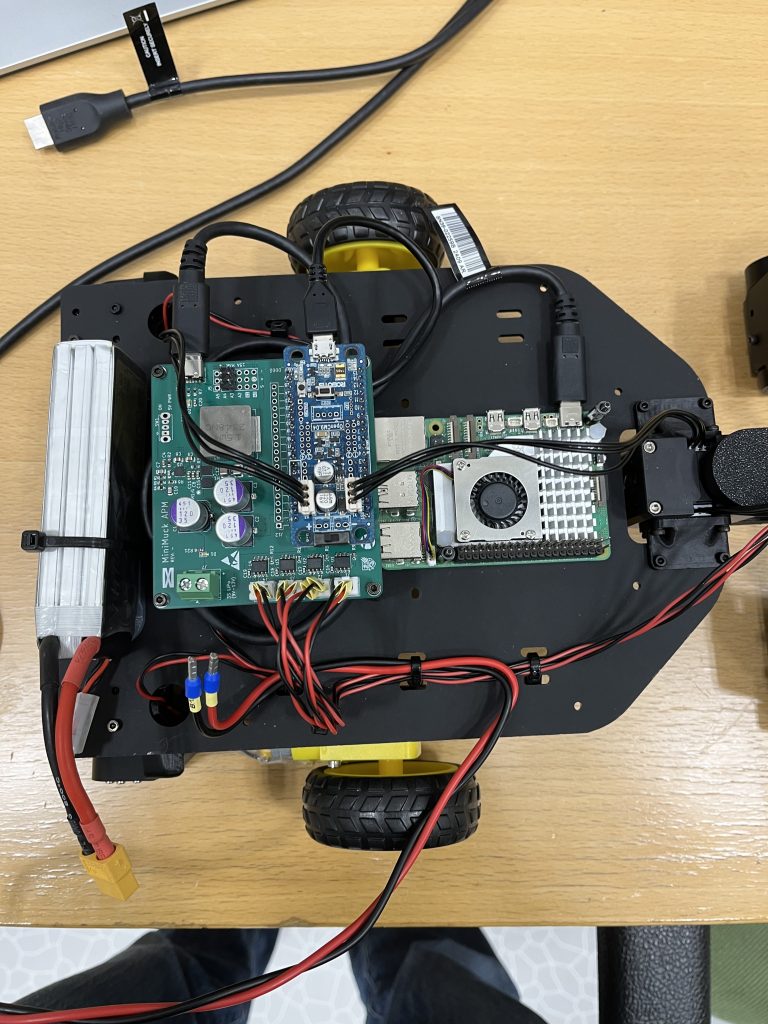
During the past week, I have finalised the electrical system by making a wiring diagram, calculating the power budget to select an appropriate battery and fixed issues with the motor and servo controller software on the OpenCM microcontroller.
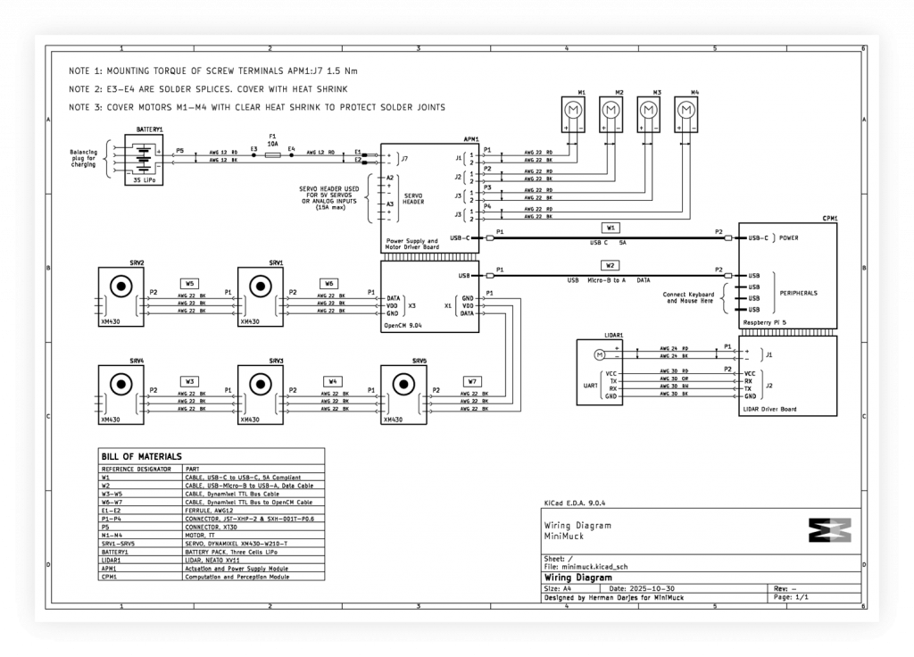
Wiring Diagram
To get a clear view of the electrical system at top level with wire connections, splices, wire gauges and cots cable assemblies, a Wiring Diagram is designed to ease the process of troubleshooting and building on the system in the future. Even if our project is nearly finished, it is best practice to draw a wiring diagram to give a clear view of the electrical system.
Power Budget
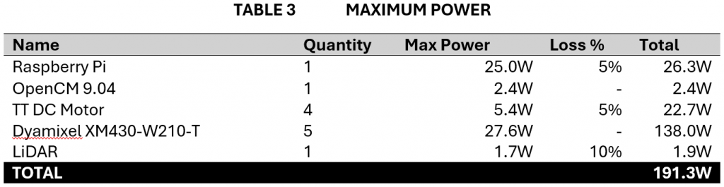
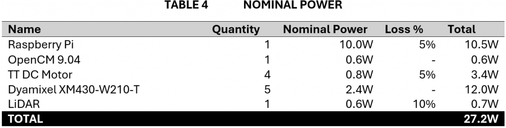
With the wiring diagram in place, it was now time to make a power budget to set the parameters for selecting a battery and fuse. Maximum and nominal power are calculated and compared to the measurements we did when testing as a verification to the budget. The maximum power is used for selecting the circuit breaker and battery max current, and the nominal power is used for selecting the battery capacity. To ensure loss is accounted for, I made a table for the loss cascade based on the wiring diagram. This gives the total amount of loss to be added to each component. The power budget is a rough estimate, not considering the nonlinearities of battery energy under different power. Tables below are extracted from the power budget document.


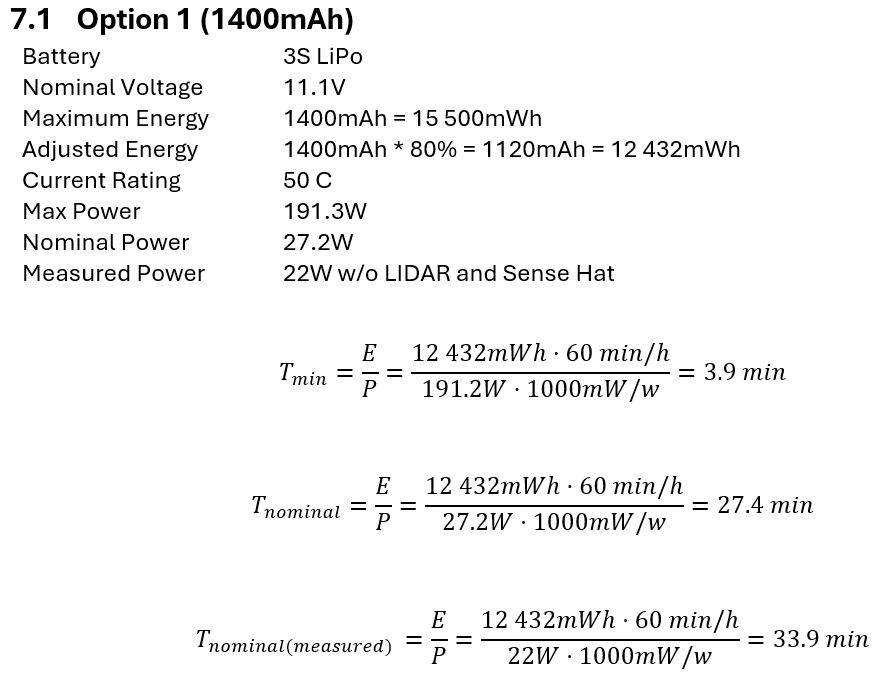

Battery and circuit breaker
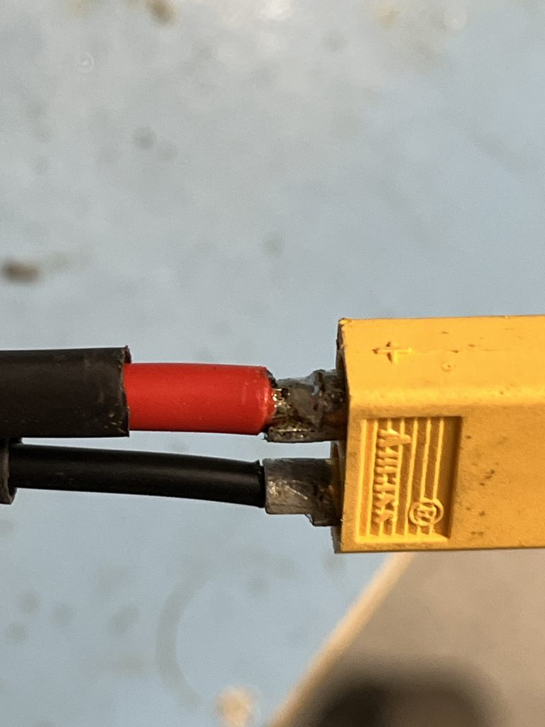
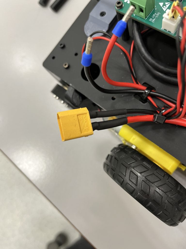
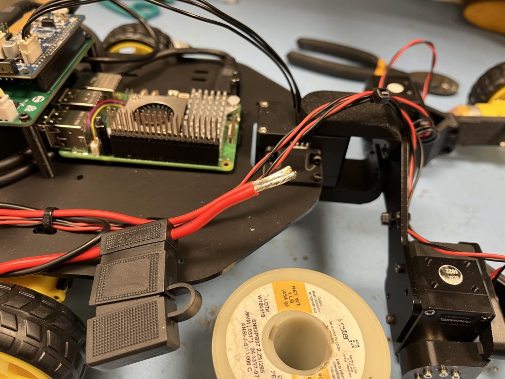
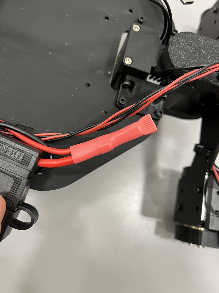
When ordering components for the PCB, I also ordered a fuse holder for standard 12V car fuse, with the plan to implement this in the wiring harness. To save money, the battery was brought from home, I soldered an XT60 connector and spliced the fuse holder wire with the wire from the power supply board and used cable ties to hold everything in place.


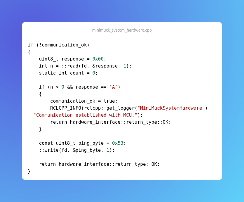
Handshake sequence
When communicating from the Raspberry Pi to the OpenCM microcontroller through UART, we send packets of three bytes at a time. If one of these bytes are not received properly, the system will stop working because it gets out of sync. During testing, we found that the system would become unresponsive at times, hence me and Leon put a substantial amount of work into troubleshooting and fixing this issue. The previous implementation was not reliable and by implementing a handshake sequence to ensure synchronisation at the start of the steam of packets require to set all control parameters of the MiniMuck. The microcontroller code was modified to check each byte individually until the ASCII character ‘S’ is received. Only now are we expecting packets of three bytes. This is implemented as a finite state machine and shown below, and the blue part is a possible expansion if we have sync issues during operation

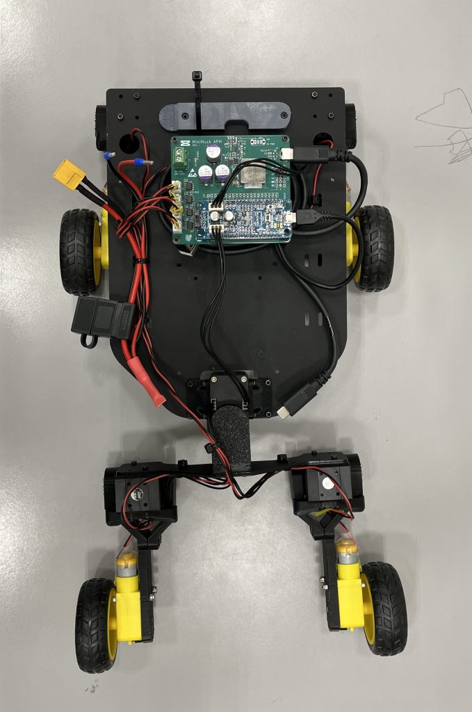
Rapid servo movement
When testing the system, we found that the servos were powerful and when the difference in goal position and present position was larger than 5 degrees, the forces introduced by the servos would make the whole robot jump.
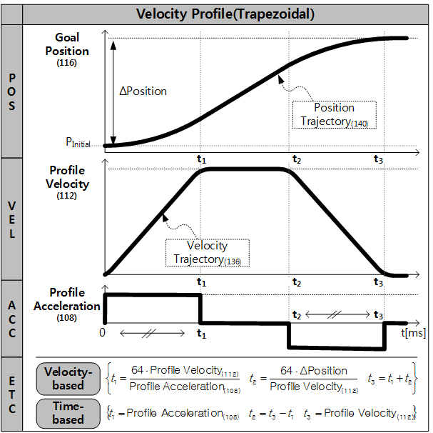
We configured the acceleration and velocity profile of the servos to reduce shock when the servos move rapidly, and thanks to the vast functionality of the Dynamixel servos, we could solve this by writing to the acceleration profile and velocity profile registers of the servo.
Next week
According to the plan, we are finishing the project next week, and i will disassemble the MVP vehicle and mount the LIDAR on the final vehicle, as this cannot be done when Ask uses the MVP vehicle to develop.
I will also attend testing and final implementation of the system together with Ask and Leon. Additionally, i will get an overview of equipment we have used so we can begin returning some of the what we no longer need.
Ask
Hei Bloggen.
Its finally working!!! This week the LiDAR is finally setup right in terms of the slamtoolbox. As the last blogs have been about slamtoolbox not wanting to update the map because of timing issues, it happens that I had more small issues than anticipated.
The week started with integration with Leon’s part, because he has been working on how the robot will move and therefore the representation of how the robot will look like for ros2 and how it moves. As this is an important part of how slam toolbox will eventually work it was natural to take Leons work and begin using it since it was finished. This took some time since Leon’s file structure had evolved so it was different to mine.
I had to make a new package for the lidar as this was the cleanest way to integrate the two parts.
After that I had to establish a static connection to the LiDAR and base_link. This is done by adding a few lines to the mm_mb.xacro file:

After this all should be working. It didn’t or so I thought. It turns out slamtoolbox don’t update before the old odometry data is updated. I thought this counted as updated if the odometry datas timestamp was updated but, it counts as updated if the odometry “moves” or the robot moves. This means that slamtoolbox wont update if the robot is “standing” still.
When I try to drive the robot around in with the digital representation this is the result:
The visuals are looking weird because the robot is standing still in the real world but rviz and slamtoolbox thinks it has moved. Therefore, maps the same points at different positions.
Next Week:
We are going to try putting all our work together and hopefully drive the robot around with mapping.
Git Lab: Mini Muck / mm software 2025 · GitLab