Hello Wørld!
This week we have left no screw unturned! The mechanics of MiniMuck is now assembled and most of the electronics are wired up. The series finale is closer than ever and by changing controller the final version is now sucessfully simulating in RViz. As usual, we’ve spent plenty of time debugging. Interfacing the LIDAR with ROS and integrating the arm movement has proven to require a substantial amount of work, but steady progress is beeing made.
Leon
Solving Challenges:
This week started with changing directions in the controller department. Together with the team I decided to swap out the ackermann steering controller (ASC) for a differential drive controller (DDC) with some code integrated into the hardware interface for steering servo. This code will turn the controller from a normal DDC controller to a DDC controller with servo steering.
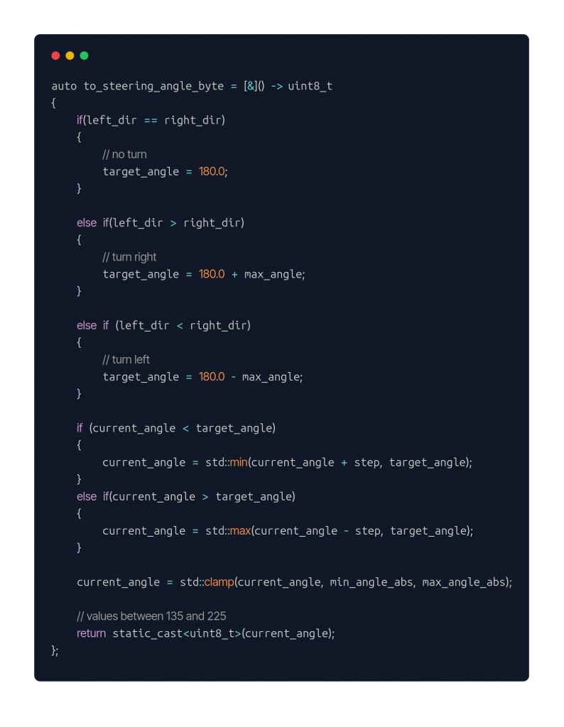
I have removed all the variable definitions to make the code shorter. But the idea is really basic this function gets called every update. Our update rate is 50Hz. The function reads data from the DDC and converts it into a turn of the steering servo. Moreover the servo does not turn all the way to the target position at once. It turns slowly with a given step towards the target position every update.
Rviz:
Before integrating the servo steering code and the rest of the hardware interface, I had to get the MiniMuck driving in Rviz. Given that I am now using a similar setup for driving as for the MVP this luckily went smoothly.
After driving around in Rviz I moved on to testing the Leg controller, with rqt. This worked smoothly.

More code:
Before starting testing in real life, I implemented functionality in the motor controller code for interpreting the leg servo commands. Here is the logic for the positioning command for the legs. It starts by converting the recived command from radians to degrees, and moves on to set the null position to 180 degrees (straight down). Then checks what side of the MiniMuck the servo is on, and converts to a value between 0 and 255 to be able to send the information in a byte.
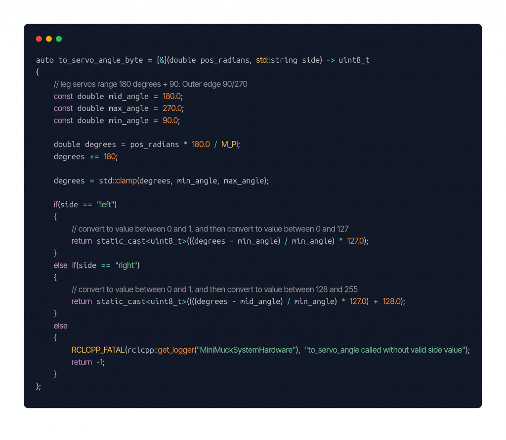
https://gitlab.com/mini-muck/mm_software_2025/-/tree/control_branch?ref_type=heads
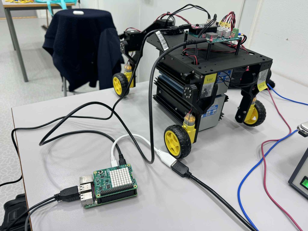
Testing:
This week we had the first testing session with the real MiniMuck. I tried using ssh from my pc to control the MiniMuck, this did not work since the inputs from my keyboard was not being read, when using teleop twist keyboard. I then tried to set up vnc, but this was not trivial with ubuntu 24.04 on the RPI. I do not view this as a huge problem since when can connect with a wireless keyboard for testing, and in the end we hopefully have a autonomus vehicle, so that we do not need continous input from the user. My plan then is to use ssh to view slam in Rviz.
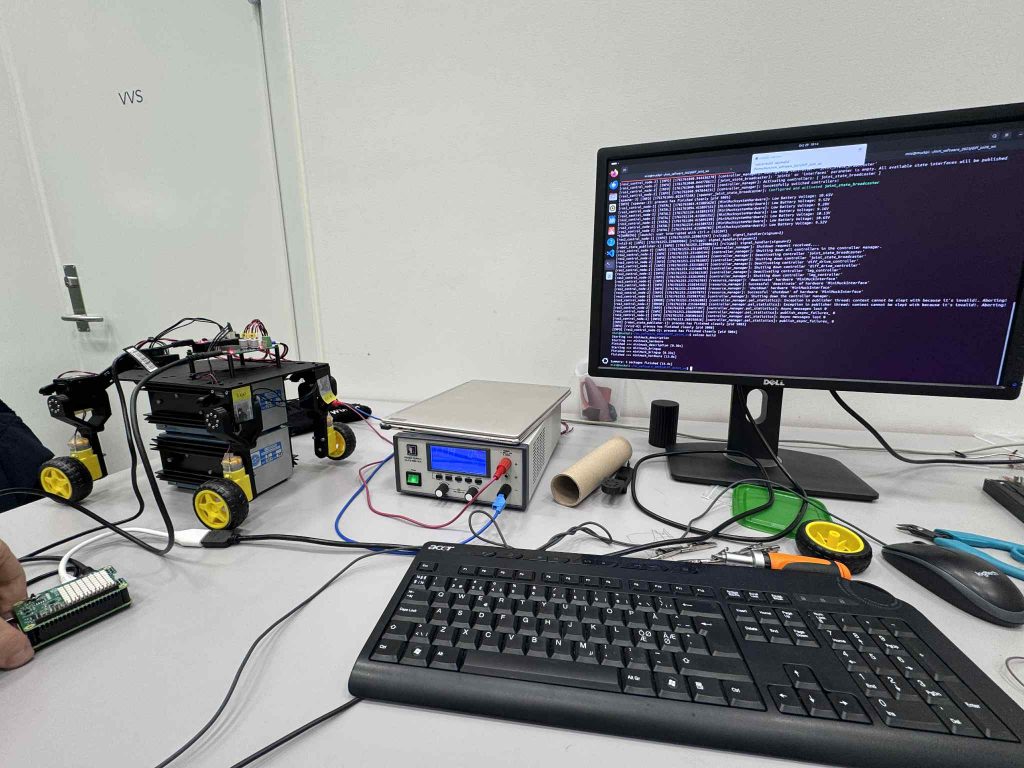
Moving on I had to make changes to the urdf file to be able to run when using the real MiniMuck, and solved the issue quickly. I tried to get rqt working to test the legs of the MiniMuck, with no luck. We also had an issue with the steering servo only steering when static, and too high starting speed for testing.
Herman
This week, I have been working on testing and qualifying the power supply under load, programmed the microcontroller in accordance with the Interface Control Document (ICD), assembled the mechanical structure together with Ask, and assembled the wiring harness.
Load Test of Power Supply
To qualify the specifications of the buck converter, I have performed a load test to test how it responds to higher currents. I have tested for steady state error (DC offset) and step response (transient load response), to ensure the power supply can handle the loads required for our project while staying within the required voltage range of 4.5V to 5.5V of the USB Power Delivery Specification Table 7.23 (USB Power Delivery | USB-IF).
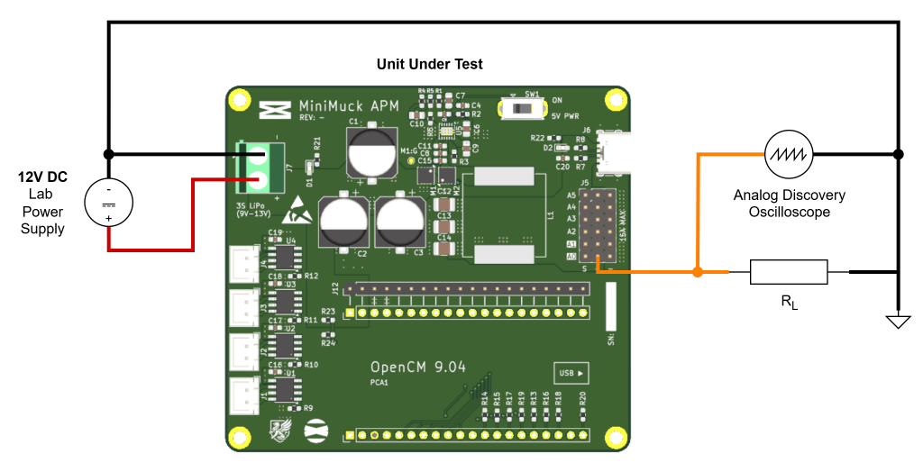
I will be using the following equipment:
- Analog Discovery (Oscilloscope)
- Lab Power Supply with voltage and current selection
- 2×8 Ohm 50W Power Resistors (RL)
- Test leads with banana plug and jack
- Crocodile Clips
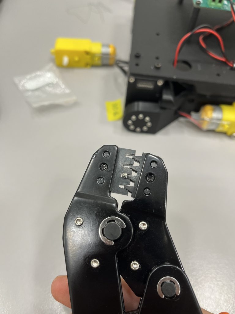
The test procedure is to solder a test wire to the 5V output of the PCB to ensure a proper connection, and to wire the 8 Ohm resistors in parallel, where I start at 8 Ohms and end at 2 Ohm resistance to test for 2.5A, which is sufficient for the Raspberry Pi.

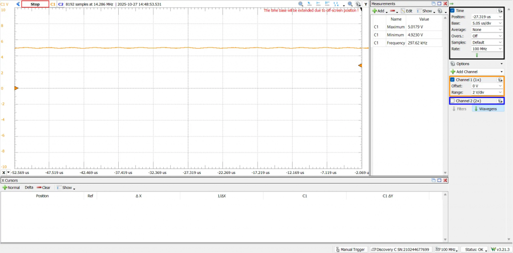
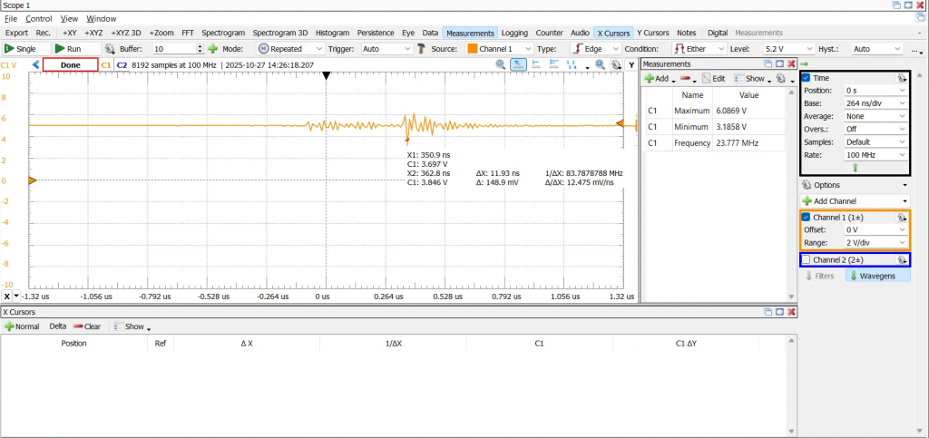
We see the voltage ramping up steadily before flatting out after about 0.2ms, without visible overshoot. The steady state voltage is measured at 5.004V, which is good when compared to the no load response, where the steady state voltage is measured to 4.990V, so we see no drop, but rather an increase of steady-state voltage in under load.
When testing by manually attaching and detaching the crocodile clip to the test lead, I got some nasty spikes. The worst one I could measure was at 3V minimum and 6V maximum, which is way outside the USB range. This can be caused by several factors such as the contact bouncing causing rapid spikes of load current, which implies the test setup is not optimal for this type of testing. If I was to conduct the test again, I would have a system to switch on and off the load current e.g. by using a transistor. Luckily after some research, the raspberry pi does not have rapid surges of current in this manner and we should be fine for this project, however I am not confident that the power supply is sufficient to satisfy high current surges caused by strong servo motors, supporting the decision to go for the Dynamixel 12V servos provided by the university.
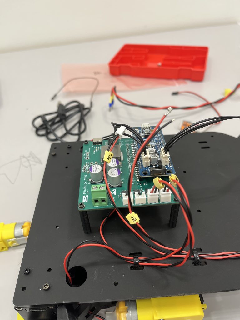
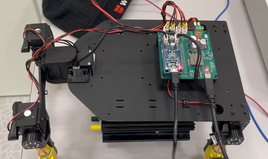
Mechanical Assembly and Wiring Harness
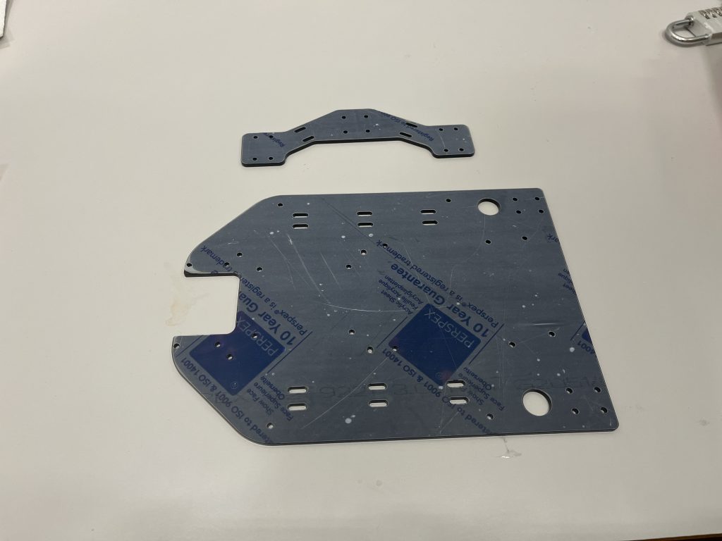
The mechanical design was finished last week. I laser cut the mounting plate and front plate, and the brackets were 3D printed by Ask during previous week. On Monday we spent some time on assembling the structure and connected the dynaixel servos to map the movement of different inputs and .
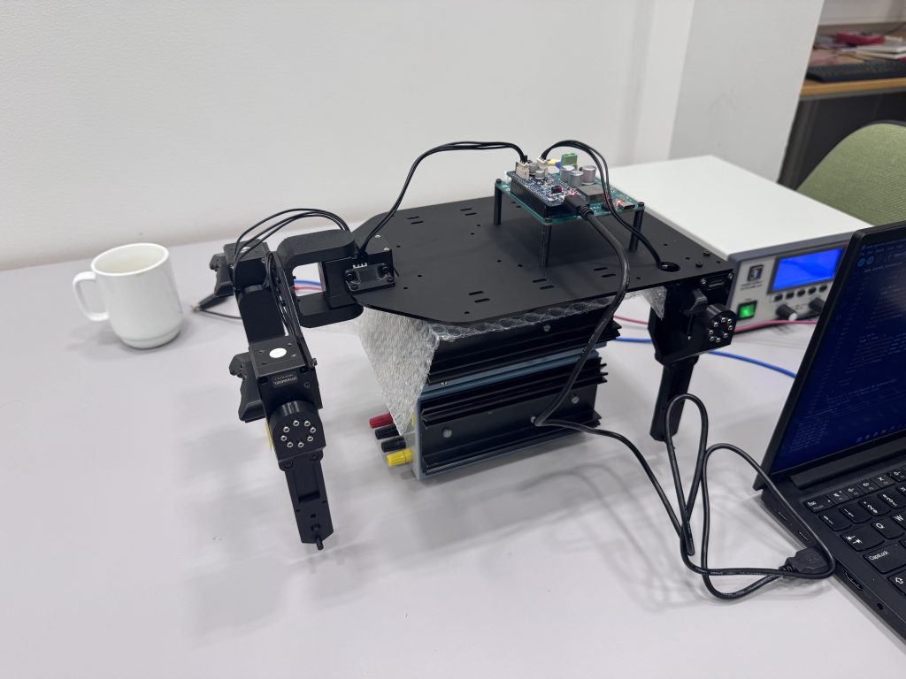
Some issues were found with tolerances on the servos, where the arm movement had friction when tightening the screws above a certain torque. We are monitoring this issue and might resolve to use thread locking compound if this becomes an issue. Additionally, there was a lot of flexibility in the structure, especially at the front, which is good for suspension, but means the vehicle wobbles when starting and stopping abruptly. I am looking into making a supporting plate for the front assembly if this becomes an issue.
Microcontroller Software
To control the motors and servos, we use a microcontroller which receives instructions from the Raspberry Pi. Because I already have acquired some knowledge about the Dynamixel servos and the DRV motor drivers, I will be developing the code for the microcontroller, which is also a good chance to work multidisciplinary.
The program will be receiving bytes over UART and storing these in variables, where the first byte is used in a switch to decide the instruction, then the operands will be used to call a function e.g. driveMotor(id, speed, direction) or setServoPosition(id, direction), which is implemented iaw. the ICD.
I also constrain the outputs sent to the servos to ensure the servos cannot be set to an angle outside of the safe operating range, which would rip the mechanics apart.
The code can be found here: https://gitlab.com/mini-muck/mm_software_2025/-/blob/apm/arduino_code/apm_opencm/apm_opencm.ino
Next week
Next week I will be making the wiring diagram, power budget, connecting the battery and adding features to the microcontroller code and fix some bugs.
Ask
Hei Bloggen.
This week I have been trying the to fix the timing issue I thought I might have. Slam toolbox has been stuck at one of the last steps “Registering a new sensor: [Custom Defined LiDAR]”. I have been trying different fixes to see if it works.
Manually making the TF Tree.
The first I tried was to see if it’s a problem in the transform tree. After some investigation I found out that the way I was trying to simulate the odom part of the transform tree the time was static at time 0.0. Slam toolbox doesn’t like this because it tries to find the right odom frame at the same time as the scan.
The solution to this problem was trying to make a own publisher for the odom frame with time that updates every time it publishes. This worked. But the problem with slam persisted.
Editing the config files.
The next fix I tried was to edit the config files for slam_toobox. Here I tried to tweak some settings, so the slam toolbox keeps more messages, so the timing issue is not that likely to exist.
This didn’t work at all. Slam toolbox is still stuck at “Registering a new sensor: [Custom Defined LiDAR]”.
Investigating if the LiDAR data is too slow.
Trying to find some different reasons for why I have this problem I came over someone saying that slam toolbox prefers a LiDAR scan with the rate of around 10 Hz. When looking at our LiDAR output I see that we output at around 4.7 Hz.
I then tried to make some dummy data and publish it at around 10Hz. This didn’t fix the Slam ToolBox problem.
All this has resulted in the first map being created at time 0.0 but no other fitting frame transform is found, and slam toolbox is still stuck on “Registering a new sensor: [Custom Defined LiDAR]” error message.
The next step is trying to implement Leon’s work and trying to redo slam_toolbox setup.
https://gitlab.com/mini-muck/mm_software_2025/-/tree/LiDARBranch?ref_type=heads