Hello Wørld!
This week from MiniMuck! The team has been in debugging hell. While producing parts, parts, and more parts. Now the whole team has full focus on the final MiniMuck robot.
Leon
The transition:
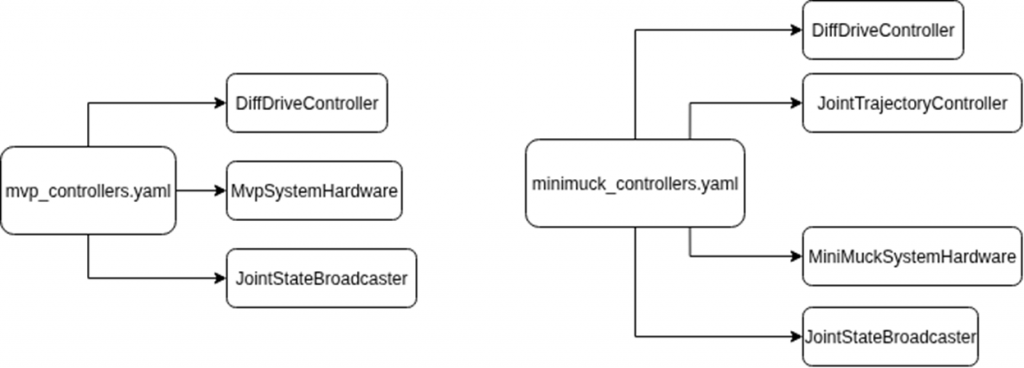
When moving from the MVP to the MiniMuck (final product) the complexity of the controller gets higher. Here is a diagram showing the stack for the MVP compared to the final product.
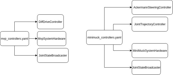
The biggest difference between the two is the fact that the MiniMuck needs two controllers. One for steering and driving the robot, and one for the arms/legs of the robot. The MVP used one differential drive controller (DDC), while in the MiniMuck we are trying to get it working using an ackermann steering controller (ASC) and a joint trajectory controller (JTC). The JTC is a basic controller where the developer has to define all components. So it is basically a framework for building custom controllers, while the DDC and ASC are controllers that have parameters they expect, so they are more rigid to work with.
Introduction:
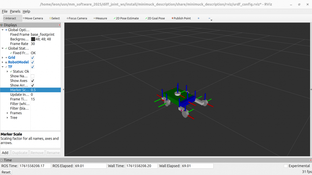
This week I have mainly worked on getting to a point where we can test the minimuck in Rviz with mock components. I spent most of monday on making the urdf and getting the right mesurements from the real minimuck. Later in the week I shifted focus to the launch file and minimuck_controllers.yaml file. the yaml file is basically a parameters file that lists all controllers with related parameters as well as the hardware used. I typically call this file the controller manager.
Challenges:
When trying to get the minimuck working in Rviz the biggest challenge I have met and still not resolved is the fact that the odomotry is not working alongside that the robot never recives the controller input from the keyboard. I assume that this is related. To start with the ASC did not even load because my parameters did not satisfy the controller. I changed and added some parameters to see if I could get it working. That fixed the loading issue, however the odomotry issue came up and is there still.
Moving Forward:
I have an idea of switching out the ackermann steering controller for a setup with a diffdrive controller, alongside some custom code for turning. I plan on lifting this idea on next weeks monday standup meeting so that we can discuss how to move forward. Moreover next week my plan is to get the robot running in rviz and be ready for testing with the real physical minimuck. That means that I have to resolve the challenges I have been facing as well as making a new custom hardware interface and launch file.
https://gitlab.com/mini-muck/mm_software_2025/-/tree/control_branch?ref_type=heads
Herman
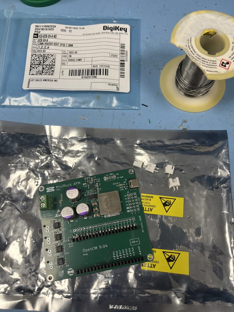
This week I have mainly worked on the PCB. The components were finally received, and I assembled the PCB with help and equipment from Timo (special thanks is in order). After assembly, I tested some of the functionality and solved issues with the design.
The Actuator and Power Supply Board (APM)
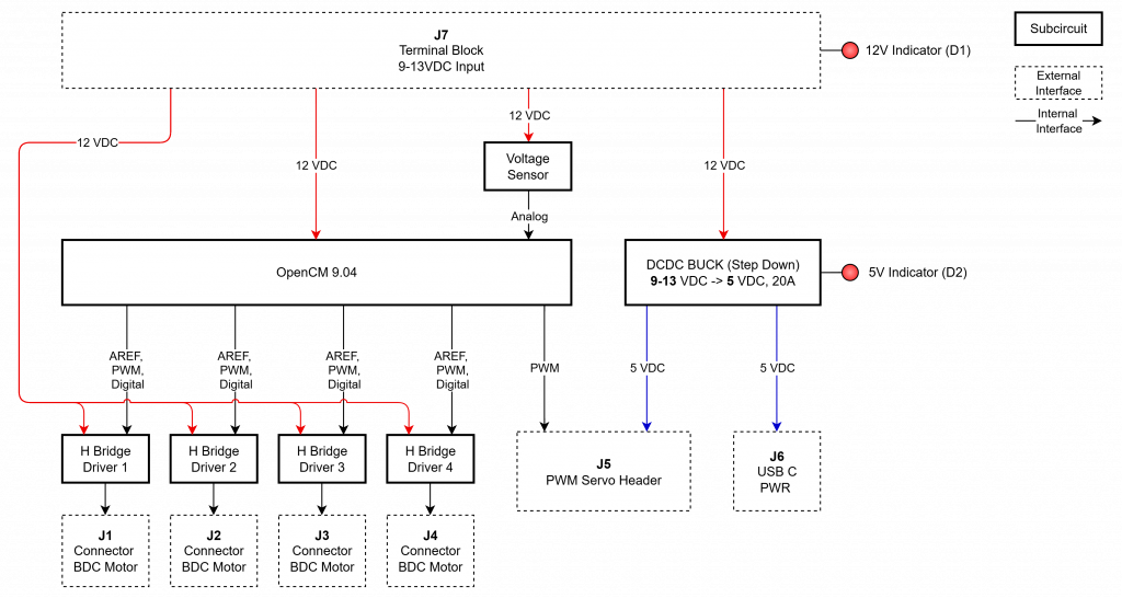
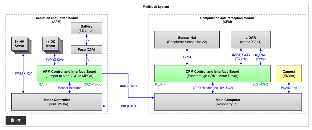
Our system uses Raspberry Pi 5 with ROS to control robotics, interpret LIDAR data and compute navigation. The Pi requires a 5V power supply, has some IO, but expansion cards are needed to control servos and motors. We are also using the Dynamixel XM servos supplied by the university with the OpenCM 9.04 microcontroller and servo driver card. By integrating this card with the Pi, we can control the servos, but external motor drivers are still needed. By integrating the OpenCM 9.04, Texas Instruments DRV8231A H-Bridge Driver, Texas Instruments TPS40303 based Buck Converter from three cell LiPo to 5V, a USB-C power connector and voltage sensing for battery monitoring, we integrate the vehicle with the Raspberry Pi on one circuit board. The block diagram of the circuit board is shown below.
Assembly
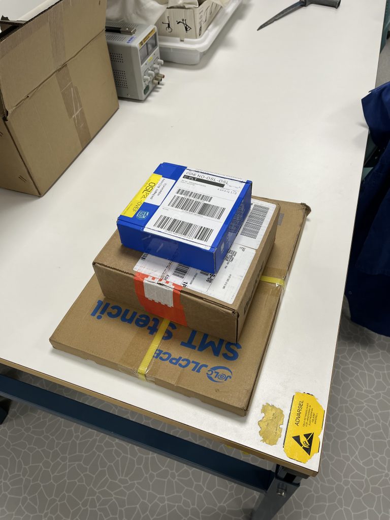
When assembling the PCB, I started with all components in bags, and the PCB and stencil for solder paste. When I ordered the components, I used the entered the reference designator (U1, R1-R4, C2, etc.) into the “customer reference” field on all lines to ease the assembly process.
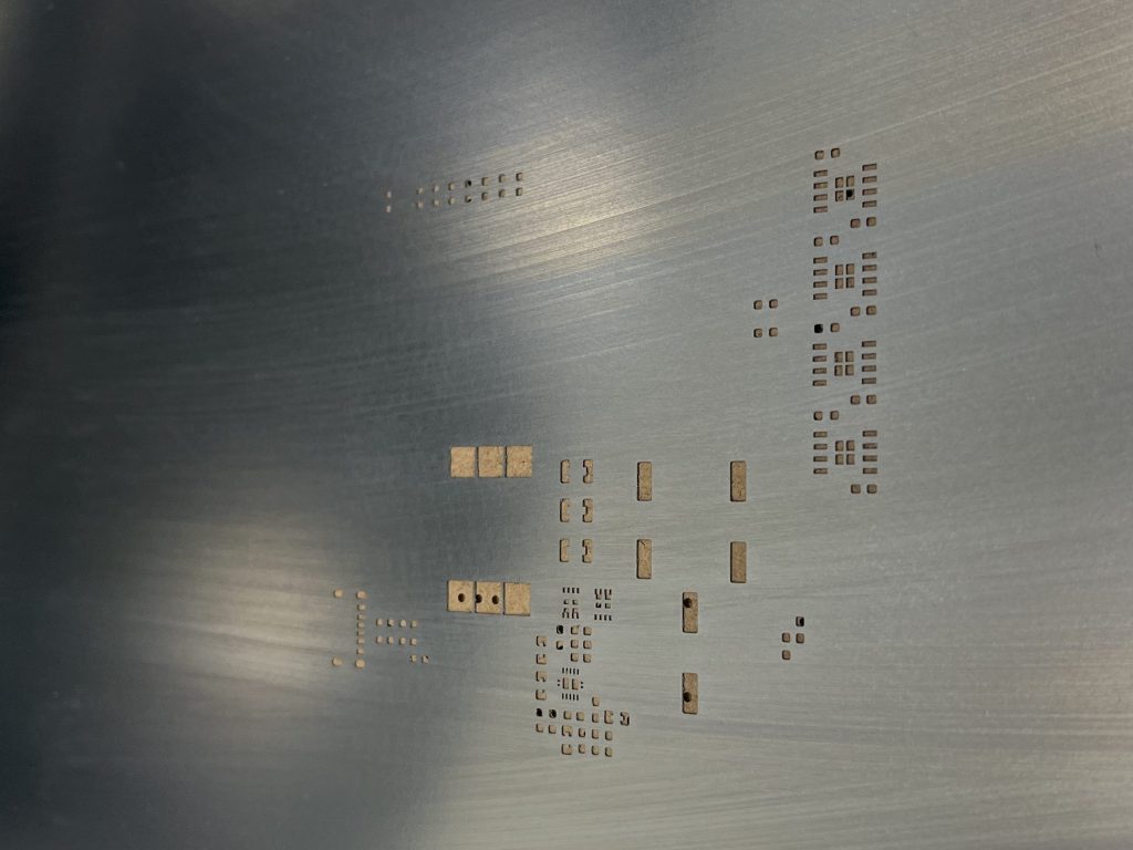
The stencil was used to apply soldering paste. The stencil design uses cutouts on pads to avoid excessive paste which can cause bridging.
A heat-bed and hot-air was used to solder the surface mounted (SMD) components. Because I stitched the copper planes, and did not use thermal reliefs, some components were quite difficult to solder. Especially the electrolytic capacitors because of the plastic melting. Because of this, a soldering iron was used on the more fragile components in addition to the through-hole (THT) components.
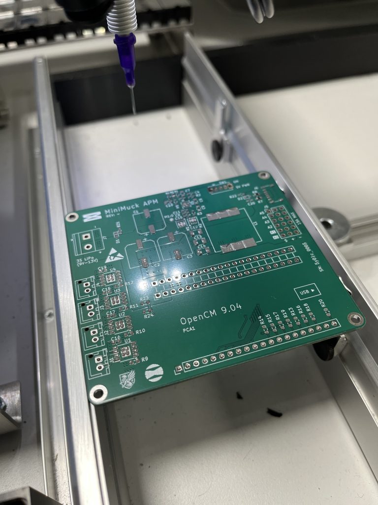
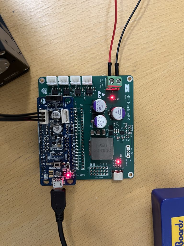
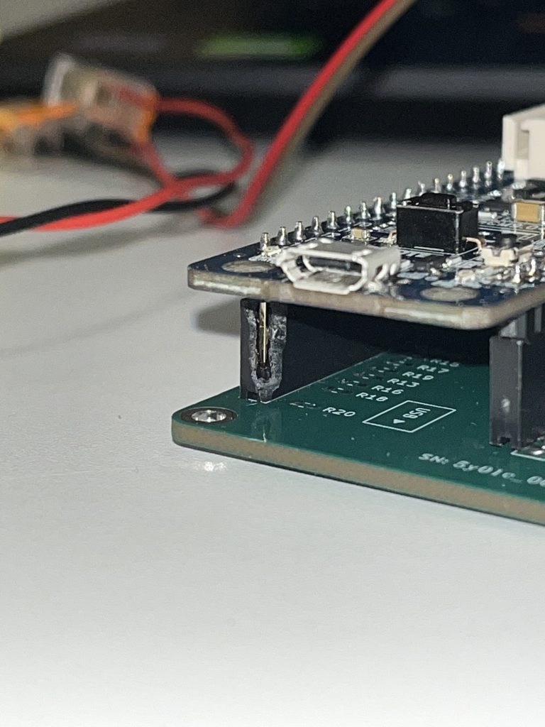
During the assembly, I checked if the OpenCM 9.04 fit, and it did not. The microcontroller does not have pin spacing in the datasheet and by counting wrong, the header was offset by one row (2.54mm). This issue occurred due to limited measurements available on the layout of the OpenCM, and I used the breadboard for measuring. To resolve this issue, the pins of the socket header were bent outwards 90 degrees like the SMD version and soldered only on top of the pads. This is sufficient for our use but is unfortunate and should not have happened.
Testing Motor Driver
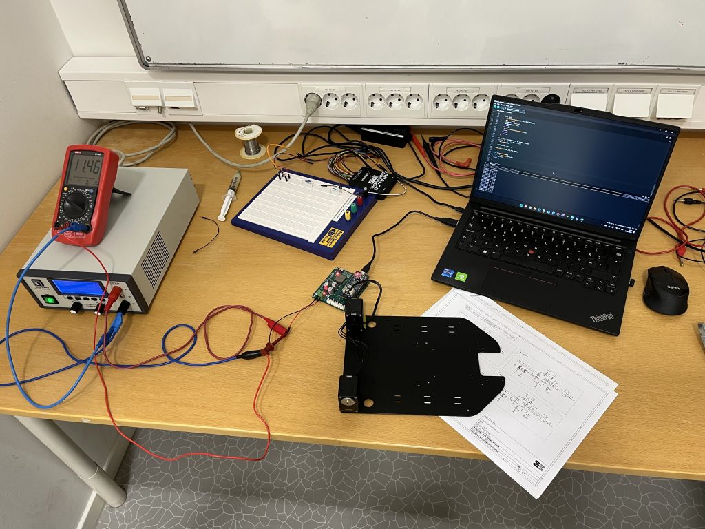
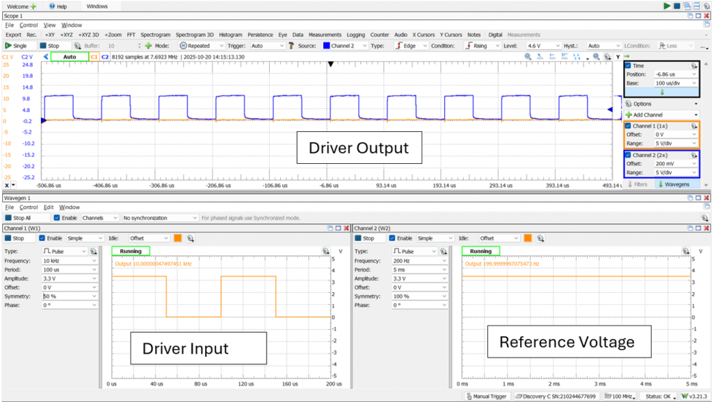
When the PCB was assembled, I did some measurements with the digital multimeter to ensure no shorts on power rails and the most critical nets were not shorted either. When no shorts were found, the power was turned on and the LEDs lit up. The power supply supplied 5V and the motor drivers amplified the PWM correctly, but there was a catch.
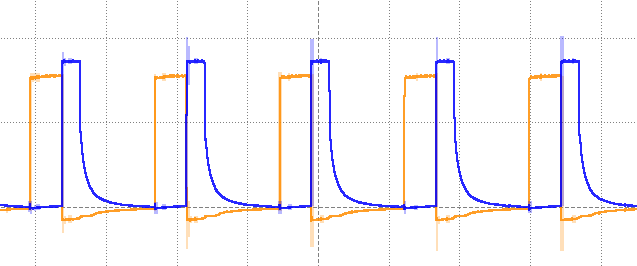
Issue with control logic
The original design was to use PWM on one pin and a digital pin on the other and this would have worked fine with a normal H-bridge, but the IC I have implemented has special functionality which sets both outputs to High impedance (High-Z) when both inputs are low. This causes issues when the digital pin is low by blocking the motor current, which causes a voltage spike on the opposite terminal and asbsorbs all the energy.
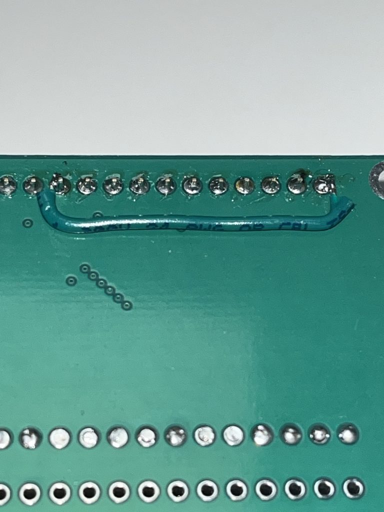
The ideal solution would be to select a different motor driver, but as a quick-fix, I use PWM on the digital pins as well, however motor driver 4 did not have this capability which was solved by soldering a wire connecting pin A5 to the motor driver IN2 and removing the socket from the header on the PCB disconnecting pin D15. A6 was originally meant for servos, but since we dont plan to use them, it was ok to use this pin for motor control instead.
First i attempted to simply connect A5 and D15 and declare D15 input, but this caused issues on startup and upload where the motor would dive at max speed uncontrollably for a few seconds. Luckily the microcontroller was not damaged by this attempt, and by removing the socket from the header on D15, the issue was resolved successfully. This incident highlights the importance of reading the datasheet thoroughly and understanding the technology before implementing it.
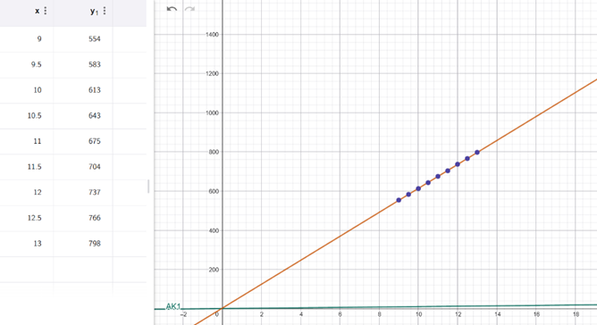
Calibrating the voltage readings
A voltage divider is used to linearly convert the battery voltage to a voltage in the range of the ADC in the microcontroller. There is a deviation between the theoretical values and the measured values. The deviation could be caused by either the digital multimeter or the ADC, but i want the ADC readings to be calibrated to the measurements of my multimeter. Hence I used linear regression analysis in GeoGebra to find the parameters to use in software.
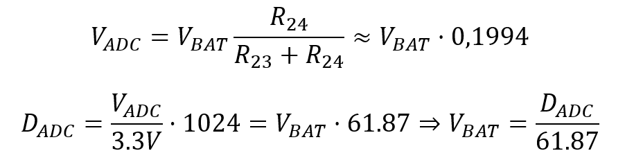

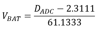
float batteryVoltage(){
  float data = analogRead(PIN_VS);
  return (data-2.3111)/61.1333;
}
Plan for next week
The next week, i plan to test 5V Power supply properly with a rheostat or power resistors before connecting the Raspberry Pi to the power supply. I also plan to help with assembling the mechanical structure where Ask has 3D printed the remaining parts. Additionally, i hope to solder motors and wire up Mini Muck.
Ask
Hei Bloggen!
Software
As mentioned in last week’s blog this week has gone to figuring out the timing issue in ros2 between slamtoolbox and LiDAR. This issue is mostly because I am working on just a part of the project. Slamtoolbox needs the odometry of the robot to make maps. I have known this since the start of working with slamtoolbox. Since I don’t have the odometry (where the robot think it is in the real world) for the robot because this is a part of the minimuck controller Leon is working on, I have simulated this using this command:
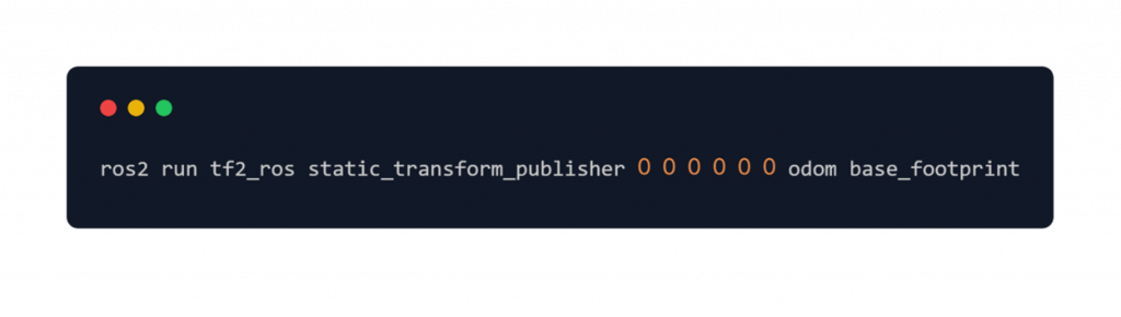
The timing issue starts here. Since this is just a static way to do this(ros2 don’t expect the robot to move) it doesn’t update the timestamp on the static odometry. This is something slamtoolbox doesn’t like as it depends on knowing where the robot is at a particular timestamp to update the map.
The solution to this is to make a publisher that I have called odomBroadcaster. This is a publisher that posts the same information as the command above but updates the timestamp in the header as well.
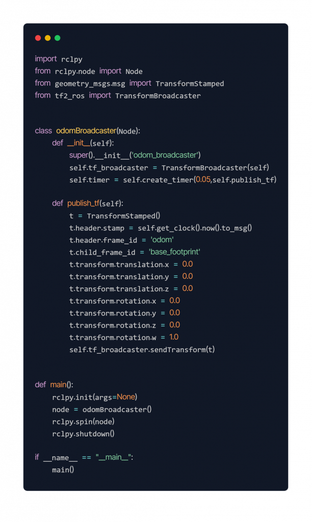
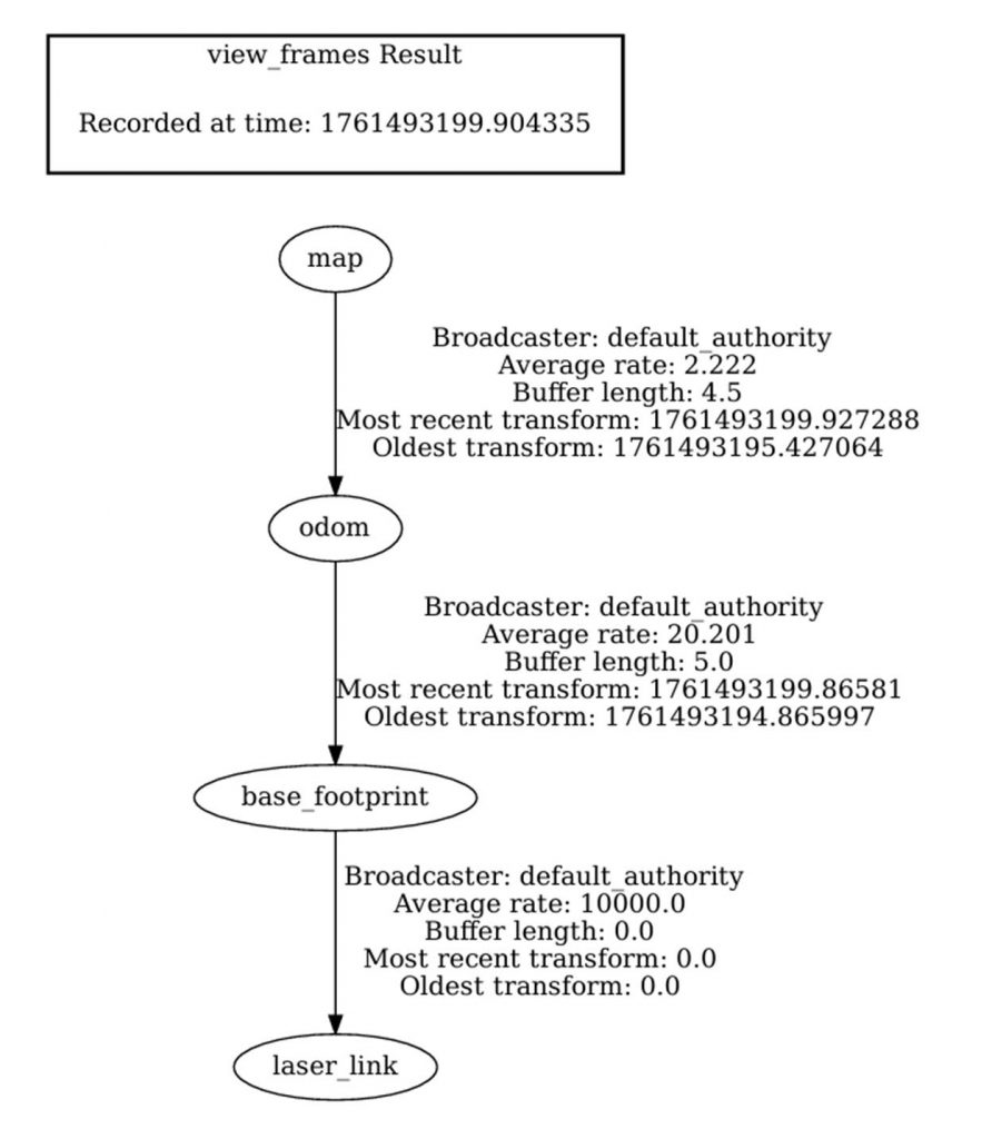
As you can see in the view frame tree all the different frames of data is correctly attached. But it doesn’t work as expected. Slamtoolbox is still hanging on Registering sensor stage. This is the next and hopefully the last stage to debug.
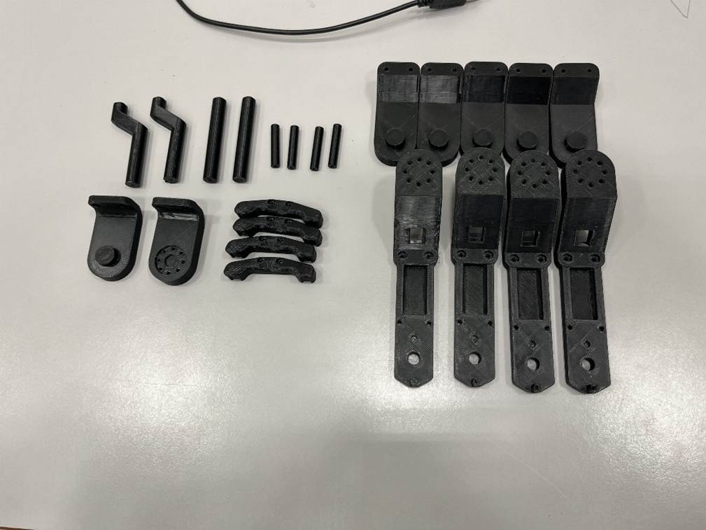
Mechanical
On the mechanical part of mini muck me and Herman have made some adjustments to hole sizes in the 3D models to fit the connectors we have decided to use and printed most of the parts we need for the mini muck. So next week we should have a finished assembly of the mini muck.
Next week
If all goes to plan next week the LiDAR mapping with slamtoolbox should work and the mini muck should have all the mechanical parts ready and assembled.
https://gitlab.com/mini-muck/mm_software_2025/-/tree/LiDARBranch?ref_type=heads