Hello Wørld!
This week the team made a lot of progress. We got the Dynamixel servos running, completed the controller for the MVP, made progress with slam, and did a whole lot of CAD, 3D printing, and laser cutting.
Herman
This I have worked with the Dynamixel servos, and together with Ask to make the mechanical structure for our vehicle.
Dynamixel Servo and Microcontroller
We have borrowed the Dynamixel XM430-210W-T from the University, which is a 210-degreee servo with about 4.0Nm stall- torque, which should be sufficient to drive the arms. With these, we have borrowed the OpenCM 9.04 microcontroller module with TTL interface, which can be programmed with the Arduino IDE by using the board file and Dynamixel2Arduino library.
Setup Guide for Dynamixel:
- Install board on Arduino IDE
- Add to board paths: https://raw.githubusercontent.com/ROBOTIS-GIT/OpenCM9.04/master/arduino/opencm_release/package_opencm9.04_index.json
- Install OpenCM 9.04 in board manager
- Run dxl-monitor from examples: OpenCM 9.04 → Dynamixel SDK → Protocol2.0 → dxl_monitor. Use the commands through the Serial monitor to configure the servos
- Scan for servos using scan to see what unique addresses are present. Servos who have the same id only show up once, and must be connected one at a time to be configured individually.
[CMD] scan
Scan Dynamixel Using Protocol 1.0
.............................................................

Scan Dynamixel Using Protocol 2.0

               ... SUCCESS  [ID:001] Model No : 01030

               ... SUCCESS  [ID:002] Model No : 01030
.............................................................- Reset using
rst2 001 - Set new unique ID on each servo on address 7 using
w2 001 007 [ID]e.g.w2 001 007 002. It is best for only one servo to be connected simultaneously. Only disconnect the servo when power is shut off and the USB is disconnected from the PC! - Enable torque on address 64 using
w2 001 064 1 - Servo is in position mode by default. Set position (dword) on addresses 116 through 119 using
wrd2 001 116 [pos(0-4095)]If the servo moves to its new position, it is working.
When scanning, one servo did not show. First, I was unsure if the servo was functioning properly, but after some trial and error, I found that when the baud was set to 1M, the servo was visible, meaning it was only configured differently than the standard. To find this in dxl-monitor, I used baud 1M.
To fix this:
- Write to baud address in EEPROM using dxl-monitor:
w2 002 008 1 - Remember to change back to
baud 57600
Now we are sure the servos are working properly and can be controlled with the Arduino2Dynamixel Library.
Using the example code, I tested the library, but got this error:
Error: Torque off failed
Error: Set operating mode failed
Error: Torque on failed
LED ON
Goal Position : 512
LED OFF
Goal Position : 2048
LED ON
After some troubleshooting, I found the issue. The code was expecting the expansion card to be connected, which uses another pin on the microcontroller. By changing these lines, the issue was fixed:
- Change
#define DXL_SERIAL Serial3toSerial1 - Change
const int DXL_DIR_PIN = 22;to28
After this, I wrote some code which takes in Serial commands over UART (in accordance with our ICD), and sets the servo angle using the input. This is shown in the video below:
Mechanical Structure
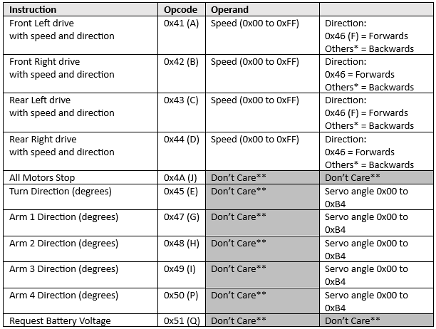
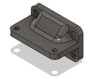
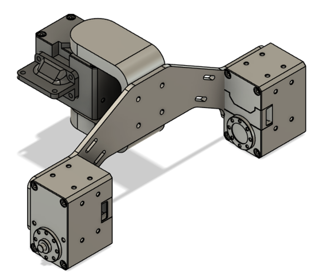
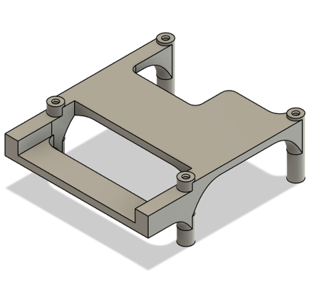
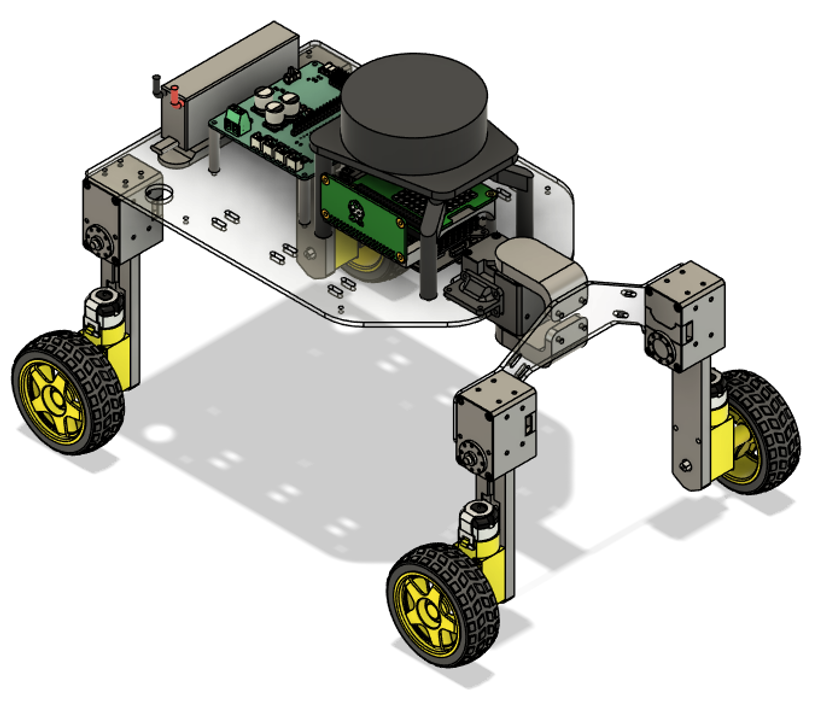
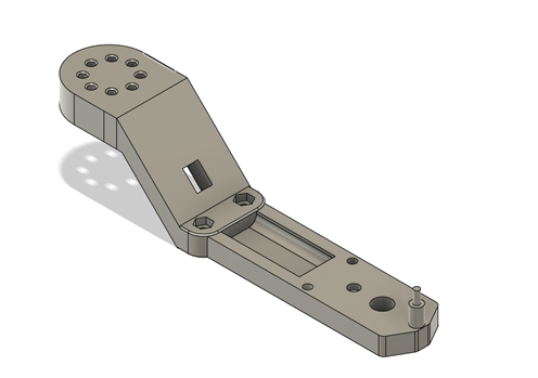
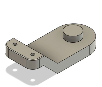
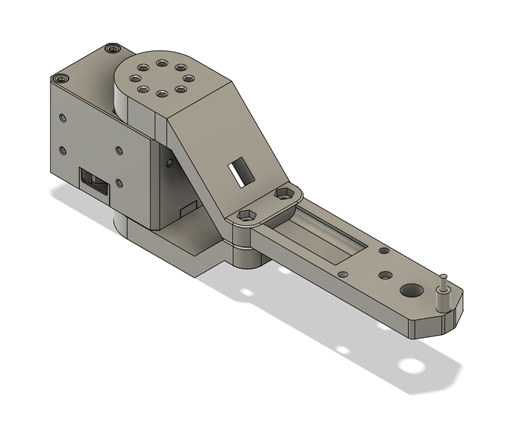
After getting some progress on the electronics, I spent some more time on the mechanical structure. The base plate will be made of laser cut acrylic sheets, while the brackets will be 3D-printed. The front assembly uses a servo for steering, and two servos for the arms. The plate has holes for cable ties. Below are all the parts of the front assembly. Ask made a brackets for the Dynamixel servo axle, so i combined these with my part to connect to the front plate. I also made brackets for the side to be mounted to the main plate.

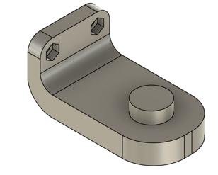
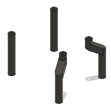
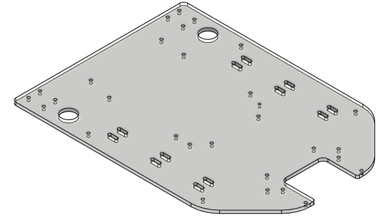
The base plate of the car has holes for cable feedthrough and for cable ties. The LIDAR is mounted above the Raspberry Pi on plastic spacers, and the Power Supply and Motor Driver board sits behind the Pi so the connectors for the servos are centered on the plate, due to length limitations of premade wires. However, if this becomes a problem, we will extend the wires. The model below uses placeholders for the arms, which Ask is designing.
Plan for next week
For the next week, I plan to solder the PCB when the components arrive and begin testing. In case the PCB does not function as intended, to an extent where we are unable to resolve it in time for the deadline, we have a plan B where we use OpenCM, prototyping board, L298N Motor Driver, Standalone DC/DC Buck Converter in similar fashion as MVP Vehicle.
Leon
MVP control
This week I got the controller to work with the physical MVP. To get this to work I switched the MockComponents that I used for the digital tests out and implemented a custom hardware interface. Moving on I updated the CMakeLists.txt and package.xml files so that they would work with my new changes.
Testing
When I had updated the support files, I moved on to testing. The testing was done statically to accommodate simultaneous development
I finally got to test the custom hardware interface, I spent some time debugging and getting the custom hardware interface working. Now the MVP is driven and controlled using teleop twist which is a ros2 node that lets you steer robots using the keyboard. Onwards the plan is to connect the controller with Nav2 and drive autonomously, moreover we will focus on doing this with the final product.
https://docs.ros.org/en/ros2_packages/jazzy/api/teleop_twist_keyboard
Launch file
After getting the controller to work with manual launch I started creating an xml launch file, to make it easy to use the MVP.
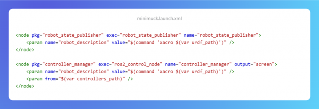
This is a snippet from the launch file, this part of the code starts up the robot state publisher and ros2 control node. The state publisher is used to display in Rviz, and the control node runs the hardware interface and controller. I have used the official ros docs for many things in this project, also for the launch file.
https://docs.ros.org/en/jazzy/How-To-Guides/Launch-file-different-formats.html
Next week:
Shifting focus to the final product.
https://gitlab.com/mini-muck/mm_software_2025/-/tree/control_branch?ref_type=heads
Ask
Hei Bloggen.
This week I have been working together with Herman on the mechanical structure of the Mini Muck , researching SLAM with ROS2 and found a prebuilt package called SlamToolBox and battling a timing issue between the slamtoolbox package and the lidar data.
MiniMuck Software
This week I have been researching ways to use SLAM with ROS2. I found a package for ROS2 called SlamToolBox that has support for the functions we want. It works like this:

The Slamtoolbox takes one full rotation of the LiDAR data in the form of the LaserScan type discussed in last week’s blog. From this rotation it makes a map of the points, Rviz then takes this map and visualizes it.
The issues I have now lie with the time on the Lidar header and the time the SlamToolBox expects. I have tried some fixes like setting a flag the creator of the slamtoolbox has made for faults like this. This didn’t work for me. I haven’t found a fix yet since I shifted some focus to the mechanical structure of the Mini Muck this week.
https://gitlab.com/mini-muck/mm_software_2025/-/tree/LiDARBranch?ref_type=heads
Mechanical Structure
Together with Herman we have CAD-ed up the Mini-Muck where I took the main responsibility of the wheel arms.
It was some adjusting for everything to line up but I have a 3D printer at home so I could test the parts quite fast and how they line up. I have also helped Herman to print his parts.
Next Week:
I will continue to 3D print and test the parts all together and hopefully have a finished mechanical structure for the Mini Muck. I also need to debug the timing issue and hopefully get a fix.