Hello Wørld! This we assembled the MVP vehicle, finally got the ROS2 Control working, got complete LIDAR data and started making the main PCB for power supply and motor control. Additionally prepared the mid-term presentation.
Herman
This week I have completed the assembly of the hardware for the MVP differential drive vehicle and worked on the PCB layout and schematics for the motor driver, servo controller and power supply board.
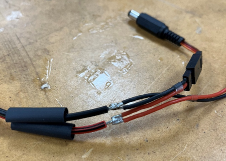
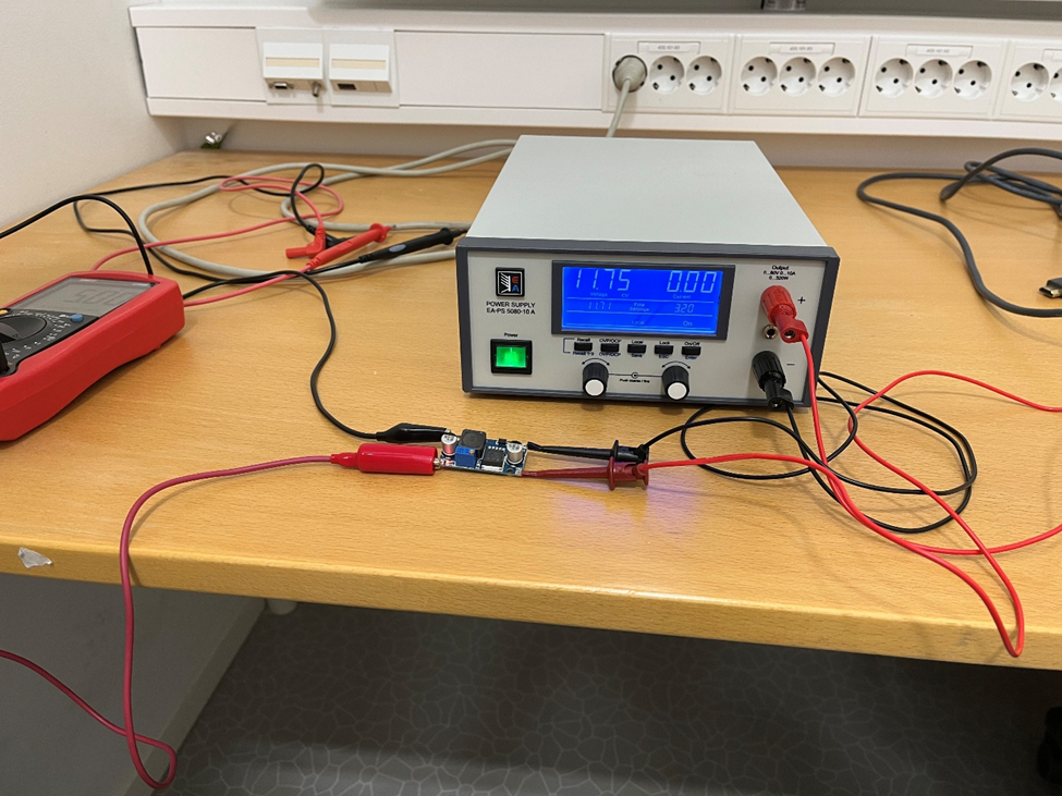
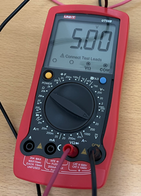
On Monday, most of the day went to assemble the differential drive car. We had 3D-printed some parts during the weekend, and the remaining parts were 3D-printed by Richard. The wiring harness was solder-spliced in accordance with the schematic from the last blog post, and covered with heat-shrink. To avoid destroying other components, I measured the output voltage and tuned the DC/DC converter to the correct voltage and checked it for the full voltage range of the 3S LiPo battery, where the results were satisfactory. During the testing, the motor solder joints broke on the wires due to metal fatigue and were soldered back on. This time, the wires were secured in place with zip-ties.
I also programmed the Arduino by combining the AFMotor library example code from with code from a previous project, to make a motor controller where instructions can be transmitted over UART to set the target speed and direction of each individual motor. Because our project is significantly software heavy, we decided it was best to leave this low-level control software this to me, as I had some prior experience with the exact functionality we wanted.
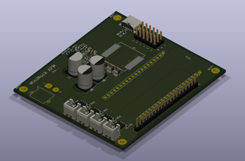
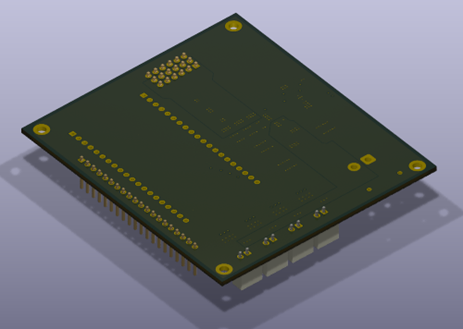
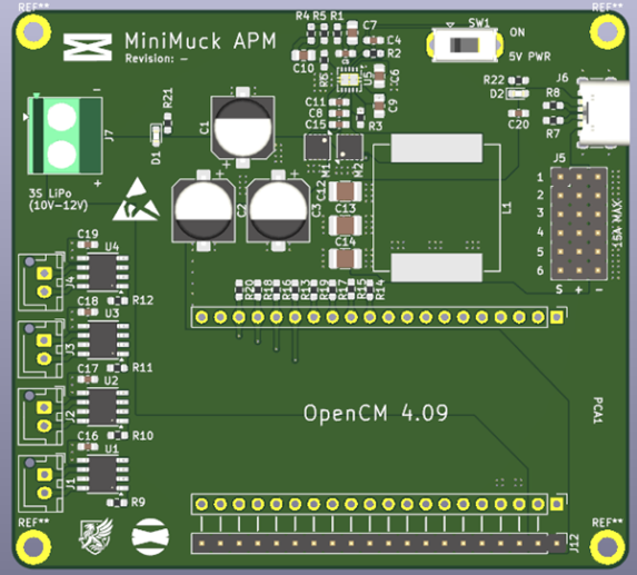
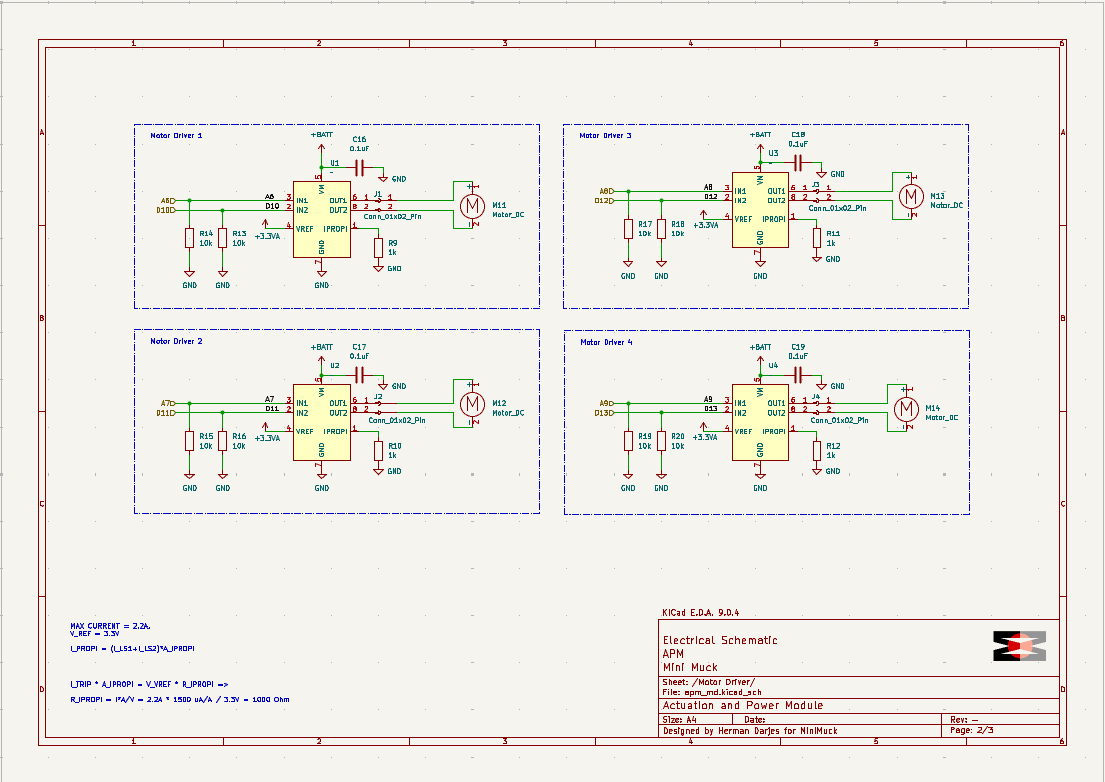
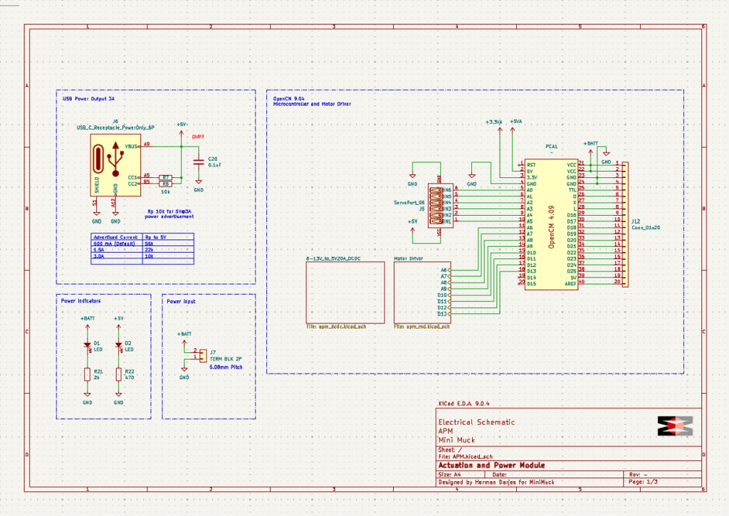
After this was implemented, I spent some time on schematics and PCB layout for the Actuator and Power supply circuit. I chose a motor driver which has two half bridges controlled with PWM by Texas Instruments and implemented one for each motor, close to the motor connector. The previous design was based around the Arduino Megas, but since we are now using the OpenCM 9.04 microcontroller to control the Dynamixel servos, the board was redesigned to fit this. I decided it was best to leave the DC/DC design as is with 5V@20A, as this is sufficient with some overhead, and the design was already checked by Ask earlier. It is safest to power the Raspberry Pi through the USB C port because of its extra protection; hence I implemented a six pin USB C power output on the board, advertising 3A to avoid a PMIC, but with config on the Raspberry Pi, we can allow for 5A, which the board can supply without a problem.
Finally, I worked together with the group on the mid term presentation. Next week I will hopefully be finishing the PCB and ordering it.
Leon
I started this week, with a goal of getting the differential drive controller to work with mock components and being able to drive in RVIZ using the keys on a keyboard. After debugging and talking with steven, and some more debugging, I got it working. This was a big win. Here you can see a video of me controlling the vehicle in RVIZ, using keys on a keyboard.
To get the vehicle moving in RIVZ I used mock components, however to get it working with the real components I need to insert them into the code and setup communication with the microcontroller, I started looking in to this, and that is the plan for the next week.
I Also used some of the groupwork day on talking with Richard and planning with the team about how to move forward and how the new scope should be. After the group collectively agreed on moving forward with the original plan of using arms on the vehicle, after getting the MVP done, I made a launch file for the controller so that I wouldn’t need to open four terminals to launch it.
The rest of the week I worked on the midterm presentation.
https://gitlab.com/mini-muck/mm_software_2025/-/tree/control_branch?ref_type=heads
Ask
Hei Bloggen
After some testing with the Lidar, I have noticed a weird behaviour from the LiDAR. The LiDAR have been outputting data with a space of 4 degrees. This behaviour was caused by a small bug in the code.
The Bug:

The fix:
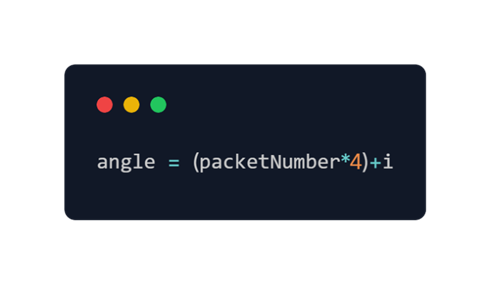
As you can see the fault was in taking out the angle data from the packet. Since I just took the +1 in the start, I just accessed the angle data for the second element in the packet. This then make sense in the data collected.
I also had the time to debug the custom message type problems. This was also eventually fixed. The main problems was typos and type sensitivities in ROS2. I have learnt that camelCase and snake_case is important to know where it is allowed or not in ROS2 as this was the root cause of many problems.
After getting the message type up and running I have found out a better way to do it. The better way is to use the LaserScan type that is a native type in ROS2.
I have also used some time on the mid-term presentation.
https://gitlab.com/mini-muck/mm_software_2025/-/tree/LiDARBranch?ref_type=heads