Hello Wørld!
Leon
This week I have focused on the controller part of the control stack. I have worked on implementing the Ackermann steering controller with the rest of the stack, then we had to rescope since we didn’t have a mechanical engineer anymore. After the rescoping, I implemented a differential drive controller instead of the Ackermann steering controller. I got some errors and couldn’t get it working, so after debugging for a while, I started looking into some camera functionality.
The first thing I looked in to was implementing the RPI camera module 3, with the RPI. I quickly found out that like a lot of other RPI devices, the camera wasn’t straight forward to implement with Ubuntu 24.04.
I tried several different methods, following different tips, git repos and YouTube tutorials, however nothing was working. All methods used some library or package that didn’t work or was based on building libcamera from source which I couldn’t get working either, I did some more research and found that using a webcam or other USB camera, may be a good option. I’ll try to get my hands on a camera like that and look more into it next week.
To see if it was just the combo of ubuntu 24.04 and raspberry pi 5 that was making everything hard. First, I tested the RPI camera module 3, and it worked with one command. Then I moved on to setting up docker and a ROS 2 container. This quickly became a nice experience because everything worked on the first try. Next step now is to try the ros2 control setup in the docker container on the pi with the raspberry pi OS on it.
https://gitlab.com/mini-muck/mm_software_2025/-/tree/control_branch?ref_type=heads
Herman
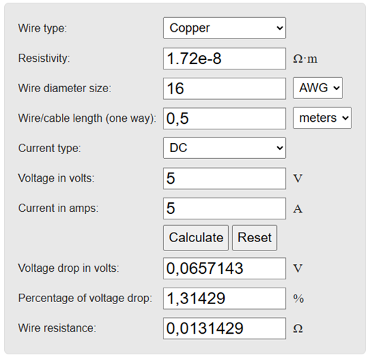
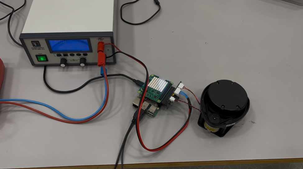
This week has been filled with both mechanical, electrical and some software tasks. Initially, the plan was to test and verify power supply through GPIO on the Raspberry Pi as the finishing touch of the Computation and Perception Module. This ended up taking way more time then expected. The Pi refused to power on, but with some research together with Ask, we found that the Raspberry Pi 5s USB-C Power Management IC (PMIC) would inhibit a boot unless a 5A power supply was negotiated on the CC pins. By adding the line “usb_max_current_enable=1” to the config.txt, the Pi now skips this check and continues booting. The relief lasted for about 2 seconds when the Pi shut down again. At this point we suspected electrical issues. We would see current ramping up on the power supply monitor before a sudden shutdown, suggesting behaviour connected to high currents. By measuring the test wires, we found them to have a total of 0.4 Ohms resistance resulting in an astronomical voltage drop across the cable. With a properly dimensioned cable using the formula below, with resistance lower then measurable with our multimeter, we were now able to test sucessfully, and reminded of the importance of proper wiring.
Voltage Drop Calculator (without temperature coefficient)
Vdrop (V) = Iwire (A) × (2 × L(m) × Rwire(Ω/km) / 1000(m/km))
After this, the remainder of the Monday was used researching the specifications and functionalities of our newly acquired servos (DYNAMIXEL XM430) and microcontroller (OpenCM 9.04) enabling us to lift the entire robot with only servos and control the servos with an Arduino compatible microcontroller.
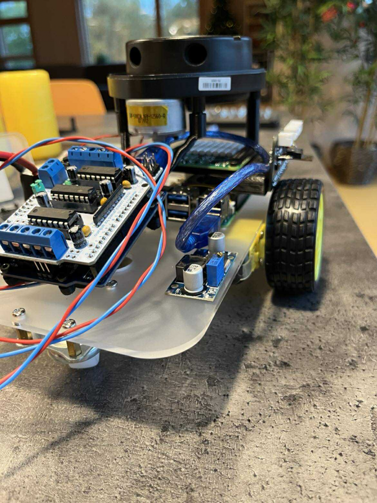
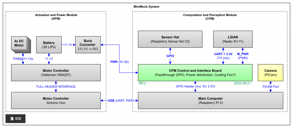
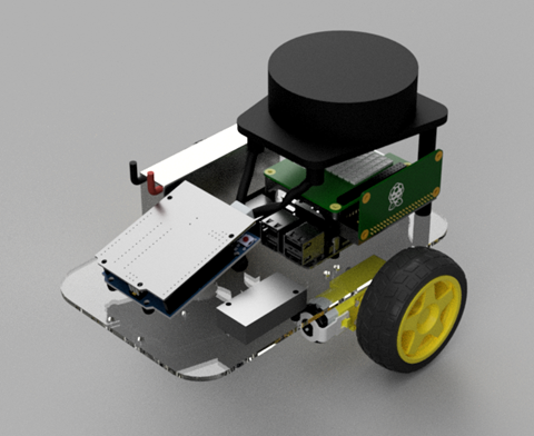
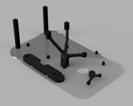
At this point we had to rescope due to changes in our group. We decided to continue building the differential drive car to ensure the LIDAR and autonomous driving development could continue with a drivable platform. By using the kit with a custom mounting plate and some simple 3D structures holding the electronics together, we can build a platform to be upgraded with a new chassis as the project continues. By using the Arduino as a motor controller, we facilitate the addition of servos and implementation of the Dynamixel servos at a later point with the same UART interface. For this new car, the electrical structure is shown below.
In the absence of a mechanical engineer, I decided to work on a CAD design for the car. I downloaded all the electronics, motors and wheels from GrabCAD, and designed brackets for mounting the electronics using Autodesk Fusion Automated Modelling to save time, where the faces are selected and a structure is generated by the computer to be space efficient while avoiding obstacles.
On Sunday, I laser cut the mounting plate and sent the 3D models to Ask for printing. We partially assembled the car this evening, which is good since Ask needs the hardware available on Monday to develop on.

During the next week, I will be working with the others to prepare the mid-term presentation and hopefully wire up all the components, fully assembling the car and develop the software for the motor controller to be controlled over UART.
Ask
This week didn’t go as planned…..
The original plan was to fix the problems I had with ROS2 and make a custom message type. This was bigger challenge than anticipated. I didn’t get the time to start debugging properly as I got a minor divergence in from of a curious Electronic engineer that wanted to test his control board that also supplies 5V to the Raspberry PI.
This naturally made it so I couldn’t work with the Raspberry PI in this testing period, so I helped debug and test. For more information about the tests see Herman’s part of the Blog.
After Monday we found out that Helle left the group. Since this is the only mechanical engineer in the group and our concept was leaning on a big mechanical part. The rest of the group then needed to rescope and figure out how we can approach the project without a mechanical engineer.
We came up making a differential drive three-wheel car. With some premade parts and some rookie CAD and 3D printing. We are quite lucky in this department since Herman, and I have dabbled in some CAD, and I have a 3D printer at home. This made it possible to start testing and printing some parts. So, Sunday evening we had this: