Hello Wørld!
Leon
This week I have worked on setting up the rest of the setup for ros2_control including setup for running a demo in rviz. I have written scripts for getting rviz and xacro files up and running through a launch file. Xacro is something I have used to get my urdf file from last week more modular. I have also separated into multiple files to get more readable code.
I haven’t got this up and running automatically with the demo script, however it works with manual input. The video below is with manual input. The problem has been that the visual figures for the individual links haven’t shown up in rviz in the automatic demo, only the individual coordinate systems for each link.
This is a part of how the software is meant to understand how the physical vehicle is. So that we further on hopefully can control the vehicle both automatically and manually to some extent.
After debugging, and not getting the automatic version to work, I concluded that I won’t spend any more time on that demo for the moment. The plan is to move on to other sides of the control stack. Next step now is to move on to finishing the hardware interface, because I have now understood that we need more than just the xacro file in the interface. And getting this running. Onwards me and ask hope to merge our work through Nav2, using the LiDAR data and ROS2_Control to try getting autonomous driving possible.
https://gitlab.com/mini-muck/mm_software_2025/-/tree/control_branch?ref_type=heads
Herman
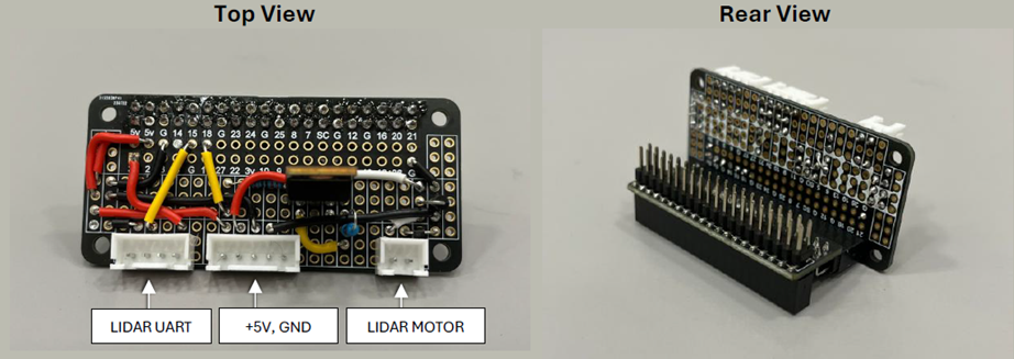
During the past week, I have implemented a fully functioning motor control card enabling the Raspberry Pi to control the LIDAR motor with PWM in a closed feedback loop.
The card is the link between the LIDAR and the Raspberry Pi with JST XH connectors for motor and UART and a power header interfacing to the Actuation and Power Module supplying 5V.
To ensure a working card without destroying interacting systems, a strict test and verification process is followed during the implementation.
- Assembly
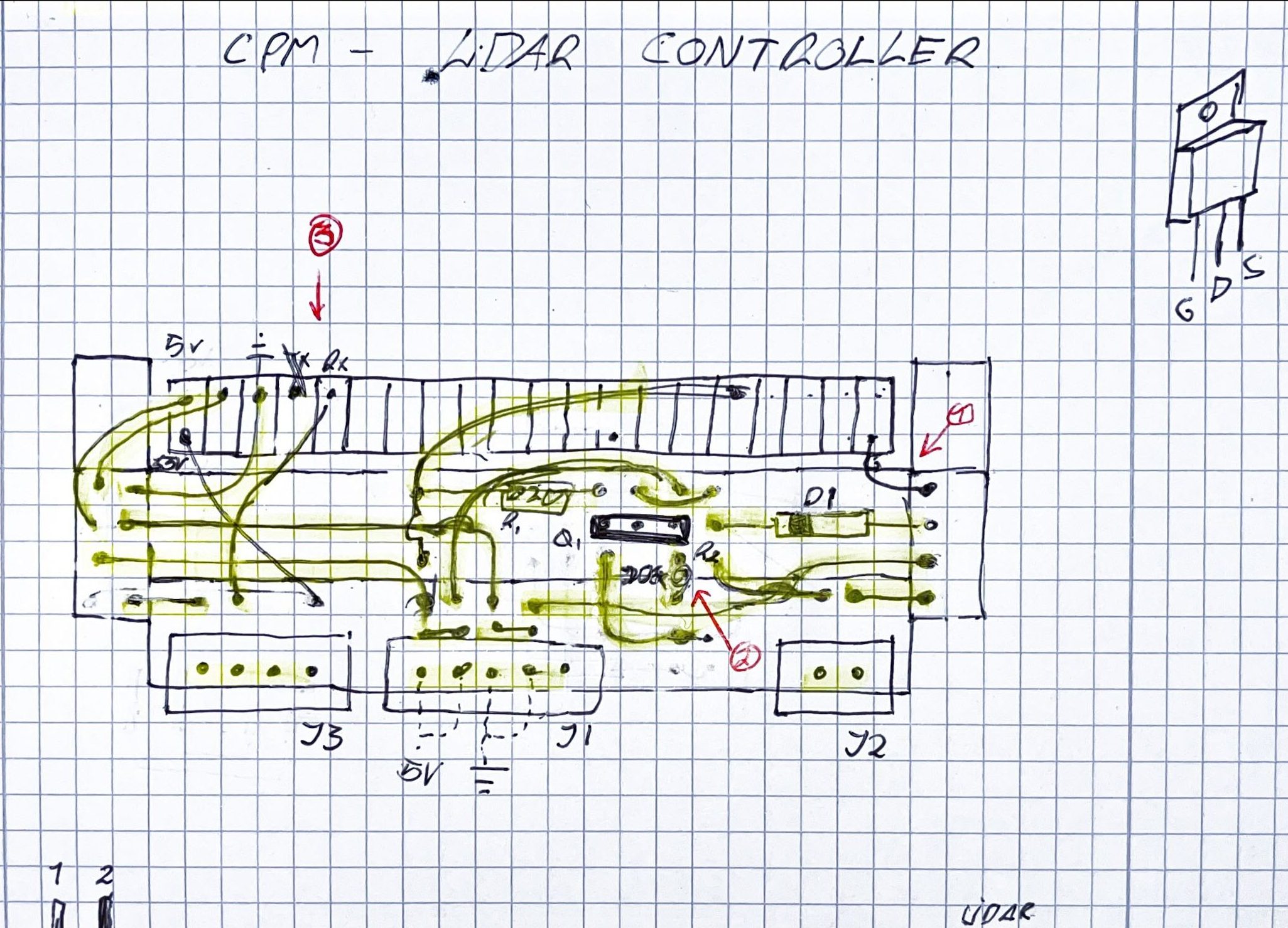
The PCB was soldered while marking the drawing to ensure all wires are in place. - Inspection
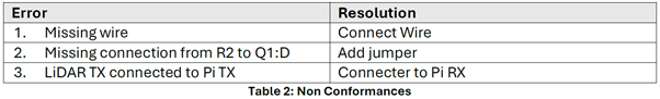
Visually inspecting solder joints for shorts and performing continuity tests to ensure all components are connected with correct orientation and polarity, and no shorts on power nets. Several non-conformances were identified and fixed. Table points correspond to arrows in drawing. - Standalone Test
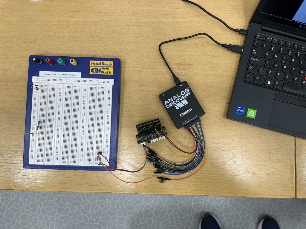
Applying power using the Analog Discovery and probing the inputs and outputs to ensure expected behavior before connecting other systems. It is important to limit power draw by using a reasonably sized load resistor.
I(max) < 20mA, V = 5V => R > 100 Ohm. I chose a 220-ohm resistor.
- In-Module Test
Testing the card with the Raspberry Pi and the LIDAR together with Ask to ensure it works as intended and we can control it with software as expected. It was useful to cooperate on this task, because there were some hardware factors which were not documented, such as the fact that duty cycle is inverted (with PMOS logic), meaning 0% duty cycle can run the motor to excessive speeds. The board has pullup to counter this, but we must still be careful with software.
Due to the PCB layout of the prototyping board and the T-shaped expansion header, there are concerns regarding the dimension of the traces and heat dissipation, which will need more testing.
Some images and tables are shown below. For the full test report, see attachment.
On Friday we received new servos from Steven. I will therefore focus on understanding these and getting them up and running for the prototype, during the following weeks.
Additionally, I plan to develop the motor and servo control card with power supply for the Pi, but the structure of this design is yet again heavily shifted from servo control to only power supply and BMS due to the new servos. I will test the card with a lab power supply to verify its robustness to high currents.
Ask
Hei bloggen!
This week started with problems. Ubuntu won’t show the pin the LiDAR is connected to so i need to find out how to access this pin. Herman also finished his electronics board for controlling the motor speed for the LiDAR. He needed some help with testing that the board actually works. So, he and I did that. To test the board, I needed to look at how to send PWM signals with the Raspberry PI. This was a little problematic at the start since Raspberry has changed how this works from version 4 to 5. Most of the documentation I found initially was for the 4 so after some testing, I found the solution for the 5 version.
Code snippet:
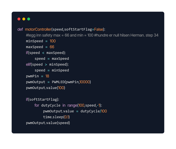
So, this is the basic function for motor control. I have chosen to include a flag for soft start this is done so you can choose if you want the motor to ease into the speed set or you can just directly set the motor to the wanted speed.
Next week I am going to focus on fixing the LiDAR pin and testing the publisher and hopefully get the RVIZ application to visualize the data to work.
https://gitlab.com/mini-muck/mm_software_2025/-/tree/LiDARBranch?ref_type=heads
Helle
This week I focused on combining solutions that reduce servo load while making the construction more realistic and robust.
Elevation
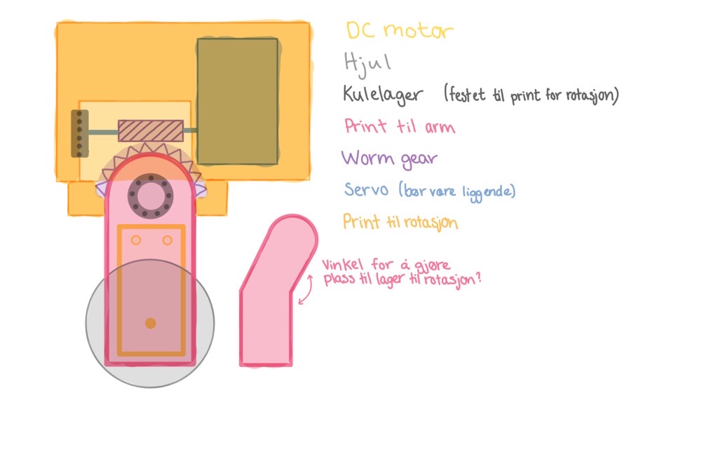
Earlier testing showed that the servos were heavily stressed when the arm was mounted directly on the shaft. To reduce this load, I explored the use of a worm gear, which is well suited for handling torque. The advantage of a worm gear is that it provides high torque while also being able to hold position without continuous power supply, which is ideal when the arms need to remain stationary in a given position.
In the sketch, the leg is shown in pink, with a DC motor driving the wheel. At the top of the leg, a gear system is included for the raise/lower function, combined with ball bearings to ensure smooth and stable movement. The servos are mounted in a dedicated block (yellow), while a ball bearing at the opposite end holds the shaft in place.
One challenge is that we do not have continuous 360° servos available. This means that gear reduction and rotational travel must be carefully balanced to avoid losing functionality. The gears can also develop heat during use, which is a concern since they are 3D-printed in PLA. However, this is considered acceptable, as the movements will not be continuous, thereby reducing the risk of material weakening. In parallel, I started 3D modeling this mechanism.
Rotation
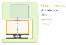
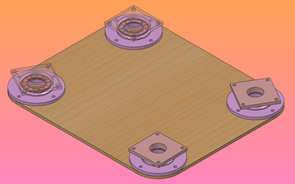
For the rotation mechanism, the servo arm will be mounted directly to the shaft, and I plan to use a turntable bearing to enable the leg’s rotation. The bearing helps absorb axial forces, preventing direct load on the servo. This improves precision, increases durability, and makes the leg rotation more robust.
The plan is to attempt building the turntable bearing myself by 3D-printing the components and using BB pellets as rolling elements.
Suspension
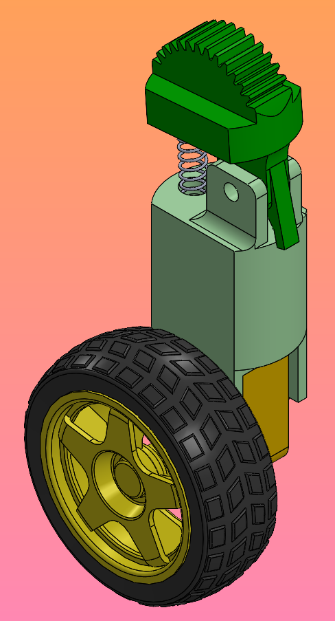
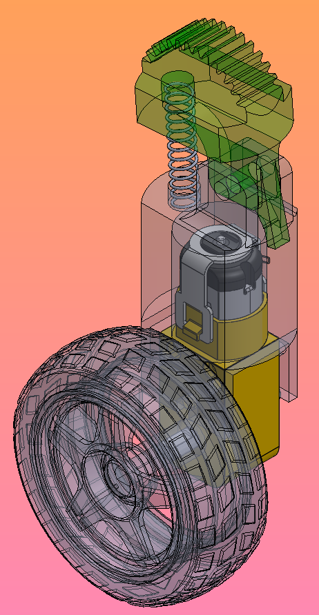

I also developed a simple suspension mechanism to make the system more dynamic. Here, I plan to use an Ø8×35 mm coil spring, placed recessed inside the leg. The spring is supported on the opposite side by a stopper, allowing the leg controlled movement within a desired range. This may improve stability when the vehicle encounters uneven terrain.
Sara