Hello Wørld!
Helle
This week I began building a physical prototype that our group can use to test servo control and motion programming. I designed a simple body in SolidWorks, integrating a joint with two servos attached to an outer segment. The servos rotate this joint to lift and lower the body, and the design allows additional weight to be mounted in order to test the load capacity of the servos. The structure is built from plywood plates, making it easy to increase or decrease the weight by adding or removing layers.
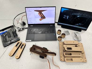
The purpose of this model is twofold: first, to test whether two servos can operate on the same signal but in opposite directions; and second, to provide the team with an early testing platform for arm positioning when the arms face each other. Having a physical system available at this stage is a major advantage, as the software team can start programming in parallel with my continued modeling [HH1] in SolidWorks. Once a more advanced model is ready, the code can easily be transferred.
Although the prototype is still quite simple, it already serves as an important tool for early-stage testing. When the team is ready, I have also prepared enough material to expand the setup and test the movement of all four arms mounted to the body.
Sara
This week i have countinued my reasearch as to what is possible in regards to the GUI. I have also started drawing a design i would like for the GUI.
Herman
During the past week, I have been in a supportive position for the mechanical engineering and software engineering.
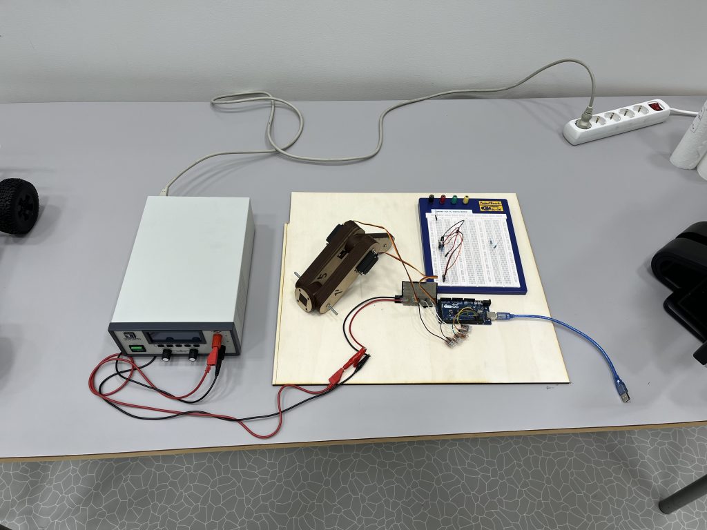
The week started with breathing life to the mechanical arm Helle designed with two inverted servos. The Arduino Mega, lab power supply, and a custom power distribution board from an earlier project came in handy for rapid prototyping. Code was developed to test the servos with serial input. From this we found that the six-armed brackets on the servo were not perfectly symmetrical, causing the two servos to combat each other in some angles. As a solution, we could either offset in software or with a mechanical offset on the angle of the bracket, but since we will be aiming to use a digital, electronic servo inverter circuit due to PWM pin limitation on the Arduino Mega, it is deemed best to solve this mechanically.
Additionally, I have been working on PCB design, by implementing a 40A 5V supply to power the servos and raspberry pi, from a TI (Texas Instruments) WEBench design to see if this is practical for us. During this week I generated the design, designed some custom footprints, and started laying components per the designer’s manual supplied by TI. Several issues were enlightened, and to name a few, the operating temperature would be around 120 degrees Celsius, the price would be well above 800kr, and the parts needed were in short supply on distributors. I have already encountered parts going out of stock while designing, and all this together made us think of different solutions.
https://webench.ti.com/power-designer/
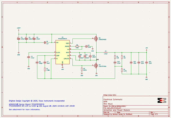
After some thought, I figured we could power the servos directly from the battery, eliminating the need for a custom power supply with such a high power dissipation and for this reason, we decided to look for servos with at least maximum voltage of 8.4 volts, so we could power this from a two celled LiPo/Li-Ion battery with a range of 6.4V-8.4V, which is now our new requirement for the battery voltage range. The design is still useful, as this can be heavily reduced to power only the Raspberry Pi and some peripherals.
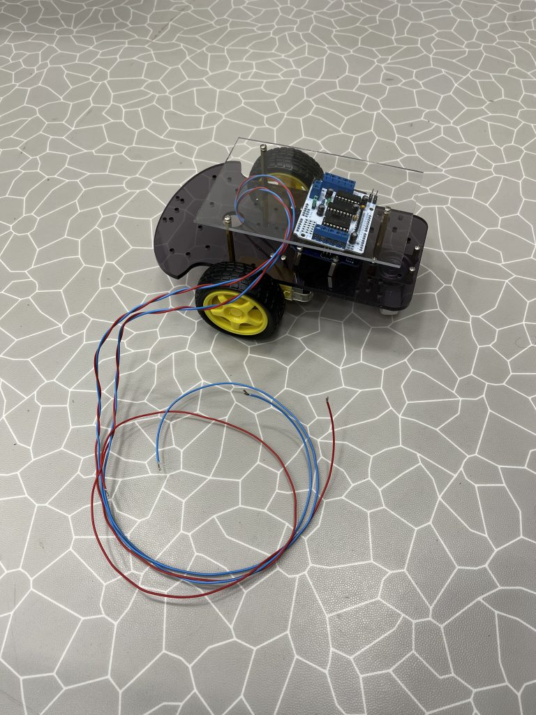
Finally, on request from Ask and Leon, I have assembled a simple two-wheel car kit (Velleman VMA500) I had from an earlier project, where two TT motors and two servo motors can be controlled from a motor controller (Velleman VMA207), to facilitate development of the software on the Arduino. Some wires were missing but were soldered back on and fastened with some putty temporarily.
In the coming weeks, I will find a proper servo motor we can order, and start designing the power supply, which now only powers the Raspberry Pi, LiDAR and some control circuitry, instead of all servos, making it significantly smaller and more manageable. Additionally, I will research making a custom battery pack from the 18650 cells available to us with a BMS.
Ask
Hei, Bloggen
This week I think that I have completed the code for parsing the packets of data from the LiDAR. The reason I don’t say fully completed with confidence is that there are probably some small tweaks and changes needed to make it fully complete and work with ROS2.
So, I started looking at some examples of how it has been done before specially from the c code from this git hub repo: ssloy/neato-xv11-lidar: Protocol description and linux implementation.
I started converting this code to a basic python implementation to test if the packet structure was the same as in the example and it seems that it was. I quickly saw that we got a lot of the same numbers as 33 ,53 ,83. The reason for these numbers is likely the flags of invalid data and strength warning.
I implemented the checks for these flags, and the numbers disappeared. This now gave us the real output of numbers we can use to map with LiDAR. In an ideal world we would get 360 degrees of samples every round the LiDAR spins. But in our case, we maybe get around 30-50 valid points per round.
After some testing with Herman, we see that the lidar is sensitive to the rpms is it to slow we don’t get readings is it too fast we get a lot of invalid readings. So, we need to find a way to adjust the rpms on the motor to the optimal rpms for the LiDAR.
The next step is to look at Rviz with ubuntu and ROS2. Rviz is a visualizing tool that comes with ROS2. This will help us validate the data we are getting from the LiDAR. We also need to find out how to use the LiDAR data so the car can drive. We have started looking at some types of SLAM algorithms and such.
https://gitlab.com/mini-muck/mm_software_2025/-/tree/LiDARBranch?ref_type=heads
Leon
This week I have finished the setup of ROS2 with workspace, packages and so on. Then me and Herman had a dialog about how to structure motor controls. Continuing, I started to research and test communication between the Raspberry Pi and Arduino. After getting that working I continued working on scripts for the vehicle, both for Arduino and RPI. Working on scripts for motor control got me to think that there had to be a better way to solve the problem, which led me to ROS2 Control.
ROS2 Control is a framework that is made to make the problem of controlling a robot easier through using interfaces that is not hardware dependent. This makes it possible to reuse code with smaller adjustments to allow for different hardware.
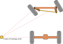
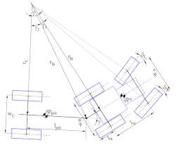
After thinking about how to control our vehicle I concluded that we should pursue Ackermann steering and implement a modified version of the Ackermann steering control from the ROS2 Control framework.
Ackermann steering links:
https://en.wikipedia.org/wiki/Ackermann_steering_geometry
https://control.ros.org/master/doc/ros2_controllers/ackermann_steering_controller/doc/userdoc.html
In between my work I have transferred some ROS2 knowledge to Ask so that he can implement the LiDAR into the system. My plan for week 4 is to find out how to use and implement Ackerman steering control for our system, as well as do more research into NAV2, which is another ROS2 framework which is used for autonomous navigation. The plan is to try to implement it with ROS2 Control.
https://gitlab.com/mini-muck/mm_software_2025/-/tree/control_branch?ref_type=heads