Hello Wørld!
Herman
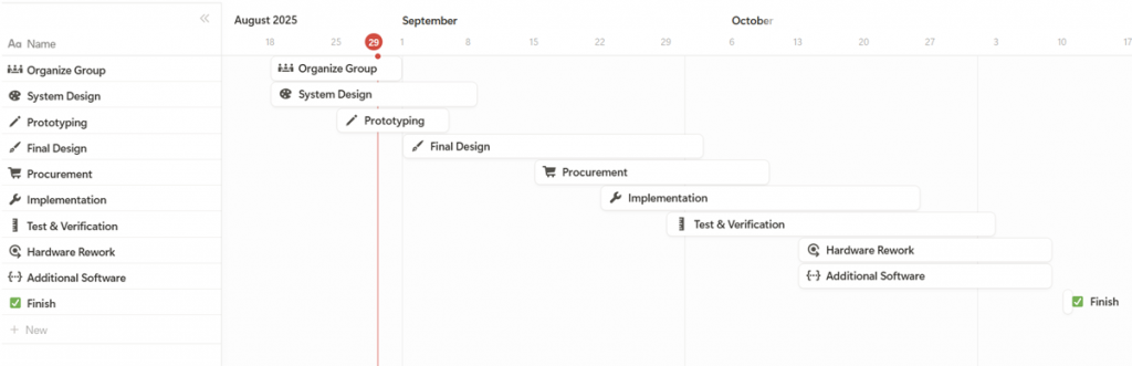
During the first two weeks, we landed the initial system design and project schedule to roughly understand the scope of our project.
As an electrical student, I was mainly joining the other disciplines in debating our project scope, while reading up on the aspects within my field. The top-level electrical system architecture was designed while researching some technologies applicable for the project, and at this point, I also outlined the project schedule from my perspective.
My responsibility is maintaining the common platform between the software and the mechanics. By designing on the two existing platforms, Arduino and Raspberry Pi, we can facilitate a parallel development between all engineering disciplines by sacrificing some freedom, and I will therefore build all electronics to be compatible with these platforms. Two of the major constraints I have been representing in the discussions, is the PWM pin limitation on the Arduino Mega, in addition to power consumption limitations we will face when designing a custom power supply.
To ensure software development can proceed, I have helped Ask and Leon by terminating the LiDAR with new JST-XH connectors due to poor connectivity in the existing connectors after excessive use over many years. To get the Sense Hat to work with ubuntu, we also had to find out why the i2c could not be accessed by the provided raspberry pi library, and solving a problem which others had faced on the internet, but no one had the answer to, which Leon will tell you more about below.
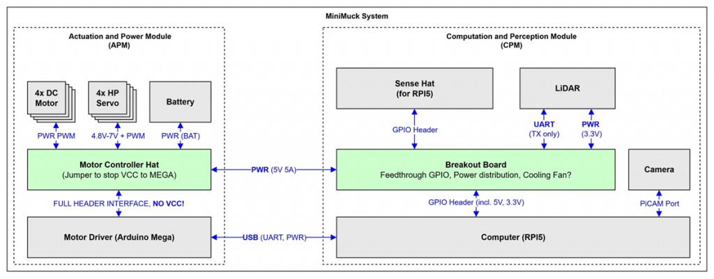
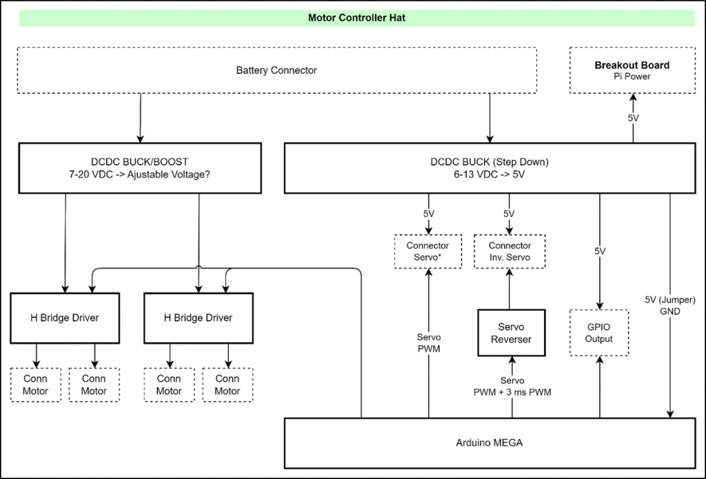
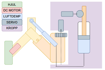
The electrical architecture was designed as shown below. From this, the power budget was calculated to put clear system requirements for our APM (Actuation and Power Supply Module), which powers both the motors and the CPM (Computation and Perception module) with its LiDAR and Raspberry Pi 5. The power budget can be found in the attachment. Interface specifications for the Pi can be found on https://pinout.xyz/.
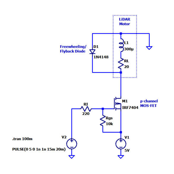
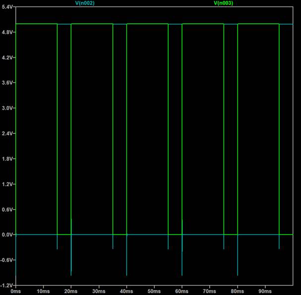
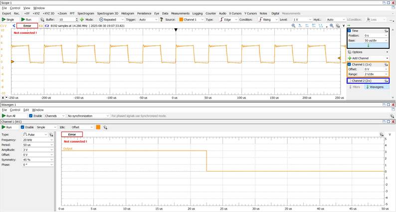
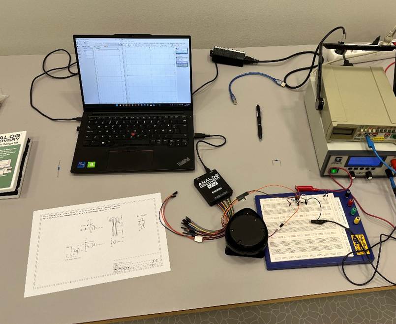
A PWM motor controller circuit for the LiDAR was designed, simulated in LT Spice, and tested with a lab power supply and the Analog Discovery for PWM generation. The test was a success because the transistor with 2-4V gate-source threshold range, could be driven with -3.3 volts, which is what we could supply from the Raspberry Pi. Parts for prototyping and implementing a shield on the Raspberry Pi were ordered from PiHut in addition to some tools, wires and general electrical components.
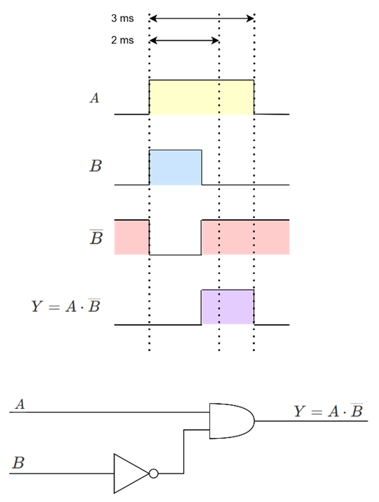
Additionally, the need to invert servos was identified, and a digital circuit was designed to handle this due to the low number of PWM pins available. (Further reading: http://robots.freehostia.com/Circuits/ServoReverser/ServoReverser.html) It is worth noting that we will not be implementing an additional PWM generator IC on the PCB to limit the scope of the PCB design.
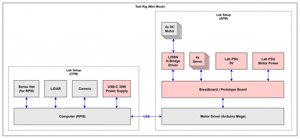
In the coming weeks, the plan is to implement a test bench for software to use with motors and servos by using the Arduino Mega, L298N H-bridge driver, Lab Power supply and breadboard, as shown in the Test Rig Diagram below. When this is completed, the work on the power supply can begin.
Ask
Hei Bloggen,
The first two weeks of the project has gone to finding out what we are going to do. We landed on a type of car with some cool “dynamic” suspension with a LiDAR on top for mapping a room.
I have started working on getting the LiDAR to work. We had no documentation on the LiDAR so google and testing if things work was the approach. At last, we found out that the LiDAR is a XV-11 LiDAR from piccolo systems. Originally used in a robot vacuum. We had some trouble getting it to work since we didn’t know what voltage it was running on and the power needed. But with the help of our resident Electrical Engineer, we found out a lot of things:
- We had some bad connections, so Herman fixed it.
- The LiDAR works at 3.3V or 5V.
- The speed of the motor is ideel at around 2.89V
- The power needed is around 150mA
And here is some links that has helped us:
The links gave us a packet structure that is normal that LiDARs use.
One packet contains 22 bytes and are structured like this:
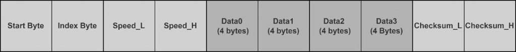
This means that one rotation of the LiDAR is 90 packets. This is because we have 4 sets of data per packet, and one set of data contains 1 degree of readings. So, 90*4 = 360.
Now the work is to code up a python interpreter of the bytes the LiDAR is outputting, so we have readable data. We are also hopefully having time to implement some type of algorithm to map and explore a room. We also must integrate this with our Raspberry Pi running ubuntu with ROS2.
Sara
Hello readers!
I joined this group this week, so the first thing i had to do was to get to know the project a bit better.
After learning from the other parties of the group what they were working on, I got to choose a part of the project to add to. I chose to make a GUI.
Having never made or learned about a GUI before, i had to do some research as to what it is, how it can be implemented, and how i can start making one. I have watched a few YouTube-tutorials and tried to code along with the video to kind of learn the basics as to how to start the actual coding for the GUI for the project.
Helle
This week I worked closely with Herman to clarify how we can adapt some mechanical principles of the Menzi Muck for our project, a spider excavator. The original machine can adapt to sloped terrain and moves with great flexibility. The cabin rotates 360 degrees. Each leg can extend, lift, lower, and rotate independently, while the wheels can rotate around the legs and are driven individually. This gives the machine unique capabilities in challenging terrain.
My focus is on the machine’s dynamic driving capabilities. To define how many motorized joints were needed, I divided the functions as follows:
- All legs can be lifted/lowered
- Front legs can rotate
- All wheels are equipped with individual motors
I created diagrams to visualise different options for the group, so we could compare alternatives. The examples shown includes both a leadscrew-based solution and a pneumatic solution. We are using a development platform with a limited number of digital pins, which favours the use of servos over stepper motors.
Together with the group, I made some priorities to make the project feasible within 13 weeks. To reduce complexity, I therefore decided to drop wheel rotation around the legs and connect the wheels in pairs, requiring fewer signals. This reduces steering ability, but allows us to test whether terrain movement can primarily be managed by leg mobility. The result is a system where the wheels are powered by DC motors, while leg rotations and lifting are controlled by servos.
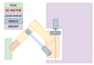
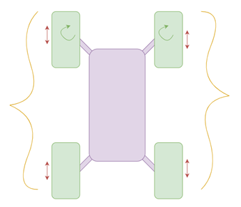
The diagram below shows the function distribution:
- Yellow: wheels controlled by the same signal
- Red: legs that can be lifted/lowered
- Green: legs that can rotate
Leon
In these first two weeks I have worked with the group on forming what we collectively want to make in this project. After we loosely defined what we wanted to do, me and Ask sat down and talked about what technologies and platforms we wanted to use for the software development part of the project.
These are the components, sensors, operating system, software and software languages that we ended up starting with:
- Raspberry Pi 5
- Raspberry Pi Sense Hat
- Raspberry Pi Camera Module 3
- Ubuntu 24.04 LTS
- ROS 2 Jazzy Jalisco
- Python and C++
- LiDAR (Neato XV-11)
- Arduino mega
Then I started setting up the development environment. I set up everything for the Raspberry Pi, including flashing the SD-card with the right OS, and downloading ROS 2 and all other dependencies for the project. On Wednesday in week 1 and Saturday in week 2 Ask, Herman and I sat down and started working on the project outline while defining our methodology and system requirements. Continuing, I set up GitLab and started to look into how to get the Sense Hat to work with the Raspberry Pi.
Getting the sensors on the Sense Hat to talk with the Raspberry Pi while running the Ubuntu 24.04 operating system turned out to be a challenge. After testing with simple scripts and finding out it didn’t work straight out of the box I started researching if anyone else had this same problem, which turned out to be the case. However, the only answer I managed to find was to change to Raspberry Pi OS, which was not something we wanted to do since RPI OS is not compatible with ROS 2.
I then started to Check out the reason for the issue, and after multiple hours alone and mostly with Herman, we found out that the I2C addresses connected to the sensors were being reserved. We concluded that the Ubuntu OS probably reserved the addresses for the sensors, however for some reason the sensors were not able access the addresses. What we did next was to force the system to free the addresses, and then my simple test scripts worked. Herman and I were literally jumping and high fiving of joy for a good five minutes after figuring this out. It was extra fun that we were able to solve a problem which others had faced, however seemingly nobody had solved.
Me and Herman also ordered electrical and other parts connected to the Raspberry Pi from PiHut.
After getting the Sense Hat to work with the Raspberry Pi and the OS, I started to get known with developing code with ROS 2. I made a ROS 2 workspace, packages and set up my simple test script as a ROS 2 publisher Node, I will continue with this and make more nodes in the coming weeks.
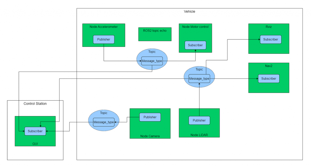
I then started looking at how we should set up the software architecture for the project and came up with a temporary software architecture diagram. We still need to look more into Rviz and Nav2, moreover we see that using these packages can be a way to hopefully achieve something cool with the project.