Welcome back to our 9th ToyzRgone blogpost! Below, you will find the contributions made by each of our team members either individually or in pairs:
Kevin Paulsen 🛠️
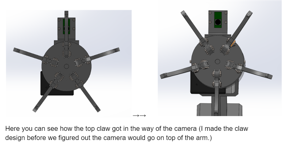
This week, I strengthened some weak spots on the robotic arm and made sure everything works as it should, especially with the gripper mechanism. I made the gripper more robust so it can handle tasks without any hiccups.
One key change was flipping the alignment of the gripper claws. Originally, there was a claw positioned right in the middle at the top, which blocked the camera’s view when the gripper opened up. Now, the camera has a clear line of sight between two claws instead, making it much easier to see what’s going on.
I also beefed up the thickness of the Servo-to-linear stick after it snapped during testing (whoops!). On top of that, I added two more fastening points for the part that connects the stick to the plate, upgrading it from one point to three. This makes the linear motion much steadier, and I can finally test it without worrying about things falling apart.
Other than that i made the camera plate a bit bigger, some walls around the servos thicker, and fixed some cut extrudes to fit better to the newly improved parts.
While I aimed for thorough documentation, it isn’t as detailed as I would have liked. This week, I had to make a lot of small but essential adjustments on short notice to get the arm up to standard for our group members who needed it ready for programming tests. Because of the fast pace, I wasn’t able to capture as much “before and after” documentation for each improvement as I’d prefer. Moving forward, I’ll work on capturing these changes more consistently.

Ruben Henriksen 🛠️
DONE:
This week I got some confirmation regarding the electronics we are going to use. We have decided that we’re going to use a Lidar scanner and it needs to be mounted so it gets maximum visibility. Additionally I have made the vehicle part slightly larger to facilitate the internal electronics, which now encompass one breadboard with drivers for the stepper motors, one Arduino Mega, one raspberry Pi and a battery pack. This list is not final and we still do not have the battery pack.
Another thing I did was to perform FEA on the stepper motor – Wheel Adapters. The previous version did break so i had to redesign these anyways. This new version is larger on the side that the stepper motor enters into. In the analysis I used 80N as the force, I based this on the weight from the assembly plus what would be max load in the not yet finished storage box. I realized that I put the entire weight of our robot on just one adapter. In theory because of weight distribution the force on the adapter should be lower than 80N.
Regardless, the results I got were promising. I got a Factor of Safety of about 2.1 with the full load on one adapter. This means that it should work and I have had these printed on the SLS printer, so we will have them next week.
TO BE DONE:
Next week I need to assemble the vehicle so that the computer and electronics can integrate their systems into the robot, and me and Kevin can mount the arm to the vehicle. I also need to design and make the storage system for our robot.
Mikolaj Szczeblewski 🔋
What was done:
This week I was hard at work of designing an SMPS buck converter circuit, which will step down the voltage from the 12V that feeds both the servos and the stepper motors, down to 5V and at 5A.
I’ve chosen the LM2678 regulator, which has the capability to operate on 5V 5A configuration at its step-down output operation.
The process behind creating such a PCB involves careful choice of components but also their placement and how to best avoid noise interferences. All of these things I’ve managed to catch a brief glimpse at.
The plan for this circuit is to feed our remaining delicate piece of electronics that we have at our disposal, and they need to be supplied at 5V. Vital components such as LiDar, Raspberry Pi and the Arduino, operate on 5V.
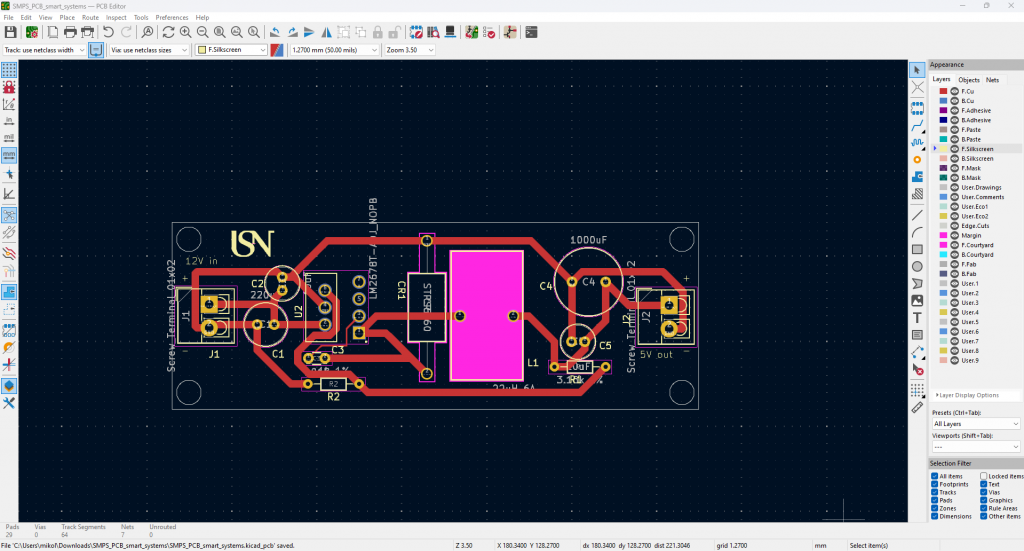
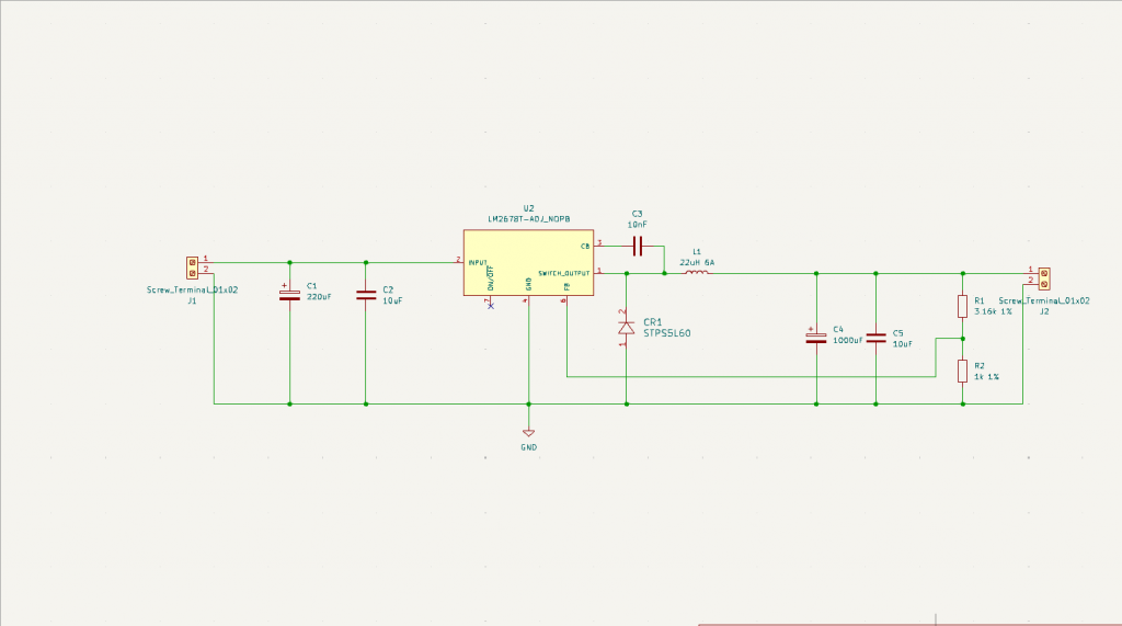
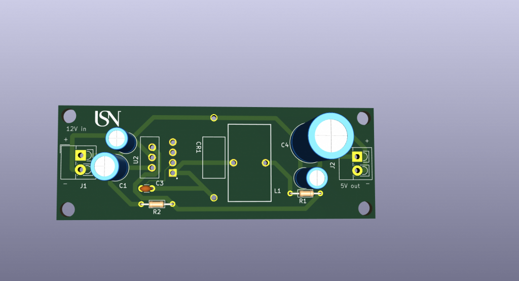
The board was designed on KiCAD which is a both professional and easy to learn program for both hobbyists aswell as engineers working in the industry.
Before the board can be manufactured however, a simulation has to be run to validate the PCB’s functionality.
Additionally, we have discussed further about the battery issue in terms of the robot’s ability to move around without being tested at a stationary condition.
Ideally, we will investigate this problem further, and potentially a battery will be created by ourselves, one that will be fed by battery cells configured in both series and parallel such that we get the required 12V and the sufficient amount of current that we deem right, which at this point is at 5A roughly.
Philip Dahl 🔋
Stepper motors
The connector issue from last week was in the process of being solved, as Rasmus had printed a piece that would fit (after some adjustments). This would allow us to finally have all four steppers running simultaneously, although it would only work for a little while.We found out that the 4th motor driver we used wouldn’t work in our circuit as it only had a 1 Amp current rating, and no adjustable potentiometer. Luckily, Ruben had another A4988 driver on hand which I swapped in. I redesigned the circuitry slightly to free up some space, placing two drivers on top and two on the bottom of the base. We are in the process of making a larger base either way, but the redesign is necessary to fit all components in the end.
I also took this time to properly adjust the potentiometers on each motor driver so that the input current fit the specification datasheet of the NEMA 17 steppers. This was not a grand task as I just needed to measure and change the resistance with a multimeter by using Ohm’s law (R=U/I). I changed each driver resistance according to the current rating of each stepper model, ranging from 1-2 Amps.
Battery
We had acquired a 12 V lipo battery that could power our robot for on the ground testing, but it was of unknown current capacity. I knew from previous tests that the stepper motors together were drawing ~0.6-1.1 Amps, depending on the velocity and acceleration. We estimated that a 12 V and 4-5 A battery would suffice for the final product. I got to borrow a lipo charger and began charging the battery with small increments, letting it sit for a while before increasing the current. I got it up to 1.6 A before testing it on our circuit and it seemed to be working just fine. I will cautiously try to charge it more to see where the capacity lies.
Sokaina Cherkane 💻
This week, my main focus was to research and implement a control system for the robotic arm(pick-up/down) with three joints operating in a two-dimensional (2D) plane. At the start I configured the servo motors in a correspondent interval, as seen in the picture below.
So that they won’t cause any disruption to the arm, if the code turn out to be uncorrect. As seen in the picture.
Since the purpose of this project is to create a robotic arm that can pick up balls, specifically, in a controlled environment. Given the arm’s limited degree of freedom (DOF) and the project’s requirements, I investigated the mathematical tools and control methods required to achieve precise movements, specifically focusing on the Jacobian matrix for kinematics in a 2D space using both forward and inverse kinematics.

To begin, I conducted research on the fundamental concepts necessary to control the movement of a robotic arm. This included an exploration of kinematics, matrix transformations, and the specific constraints involved in our setup. Since our project involves an arm with three joints moving in a 2D plane, it became clear that I would not need to account for the Z-axis. The arm will only operate in the X and Y planes, as the robotic car to which the arm is attached will handle positioning and orientation. This setup allows us to focus solely on the arm’s control over the X and Y axes, reducing the complexity of the kinematic model.
Understanding and Adapting the Jacobian Matrix for 2D Space
Through my research, I discovered that a Jacobian matrix is essential for controlling robotic arms, as it allows for the transformation of joint velocities into end-effector velocities. This is especially useful when the goal is to control the end-effector (the hand aka gripper of the arm) to move smoothly and accurately to specific coordinates.
The Jacobian matrix is essential for calculating the necessary joint movements to achieve a desired position or motion path in the X and Y coordinates.
- Jacobian Matrix
Let me break down a simple explanation of the Jacobian matrix, as I understood it. It represents the relationship between joint velocities and end-effector velocities. For a robotic arm, it translates the angular velocities of the joints into the linear velocities of the end-effector in Cartesian space. In a 2D system, the Jacobian matrix for a three-joint arm is typically a 2×3 matrix (since we have two output velocities in X and Y directions and three input joint angles). It effectively tells us how the changes in each joint angle will affect the position of the end-effector, which is essential for coordinated, precise movements.
2. Adapting the Jacobian Matrix to Our Project
To apply the Jacobian matrix to our project, I needed to consider several components:
- Kinematic Joint (Kj): This represents the kinematic characteristics of each joint, including its rotation axis and position.
- Transformation Matrix (Transform): This matrix translates each joint’s movement into the Cartesian plane for the end-effector.
- Screw Axes (se): These are the directions of each joint’s rotation in space. Since we’re operating in 2D, we simplified this to only account for the X and Y axes.
- Jacobian Column: Each column in the Jacobian matrix corresponds to the influence of a particular joint on the end-effector’s position. For our setup, this meant calculating the partial derivatives of the end-effector’s X and Y positions with respect to each joint’s angle.
Using these components, I constructed a Jacobian matrix that allows for precise control over the 2D movements of the robotic arm. By applying this matrix in our code, we can convert desired end-effector positions into the necessary joint rotations and movements.
Next week:
Implementing the mathemathical calculations into C-code.
Hamsa Hashi 💻
This week, my focus was on enhancing real-time video streaming between my Raspberry Pi 4 and a Windows-based machine. Given that object recognition on the Pi Camera Module V2 is limited by resource constraints. The goal is to use the YOLOv8 model for object recognition with minimal latency. Here’s a detailed breakdown of what was done, the code improvements I implemented, and the challenges I faced.
Setting Up the Raspberry Pi as a Client
I started by setting up the PiCamera2 on the Raspberry Pi to record video at 640×480 pixel resolution using the RGB888 format. This format ensures that the video captures a lot of color detail. Then, I sent these video frames to a Windows computer using a TCP connection, which is a “reliable” way to transfer data between devices. This forms the basic structure of my initial setup:
#Oppsettet av Cam:
picam2 = Picamera2()
picam2.preview_configuration.main.size = (640, 480)
picam2.preview_configuration.main.format = "RGB888"
picam2.start()

# TCP connection til host(Windows:)
client_socket = socket.socket(socket.AF_INET, socket.SOCK_STREAM)
client_socket.settimeout(20)  # Legger til en timeout for forbindelsen
client_socket.connect(('192.168.1.145', 8000))
connection = client_socket.makefile('wb') # writeBinary

# Streame på bilde frames:
try:
    while True:
        frame = picam2.capture_array()
        connection.write(struct.pack('<L', len(frame)))
        connection.flush()
        connection.write(frame.tobytes())
Challenges and Improvements
While the initial code successfully transmitted video frames, I faced significant issues, such as network interruptions and high latency. To address some changes I have tried out:
I modified the client-side code to handle network failures gracefully and attempt to reconnect automatically if the connection dropped. This was crucial for maintaining a stable data stream. I balanced the resolution and frame rate to reduce the network load without sacrificing too much image quality.
Improved Code Snippet with Error Handling ->
# Funksjon med feil behandling
def send_data(connection, frame):
    try:
        connection.write(struct.pack('<L', len(frame)))
        connection.flush()
        connection.write(frame.tobytes())
    except (ConnectionResetError, BrokenPipeError) as e:
        print(f"Error: {e}")
        return False
    return True
Windows Server Setup for YOLOv8
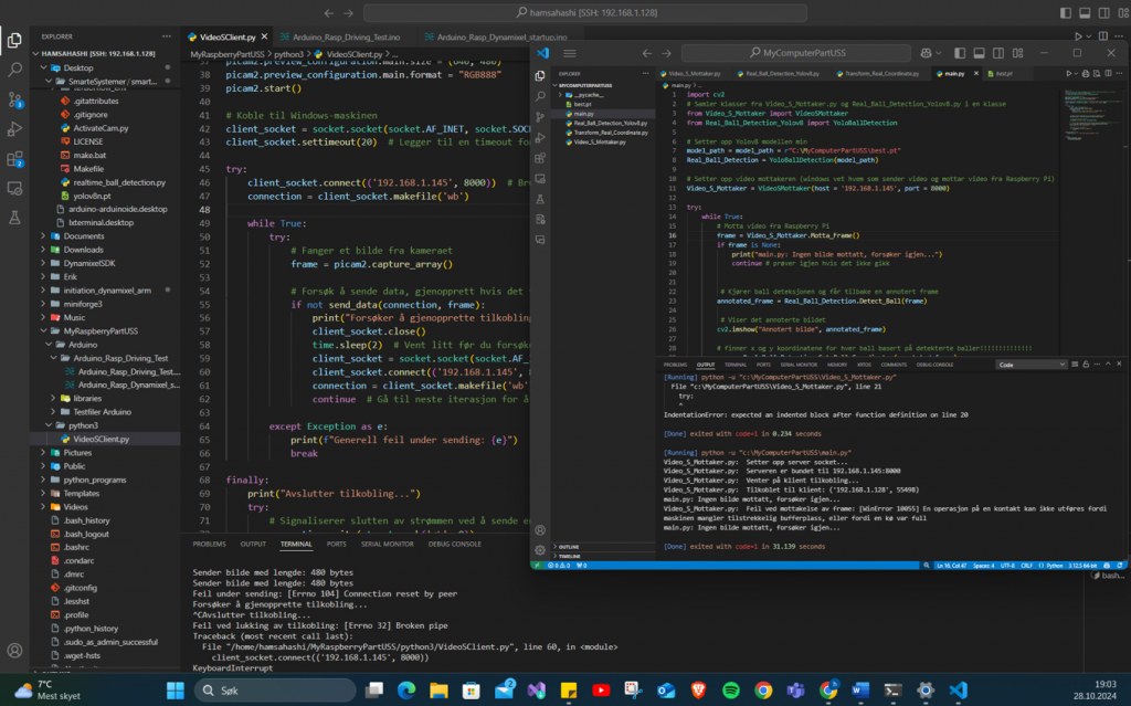
On the Windows side, I set up a server to receive video streams from the Raspberry Pi and run YOLOv8 object detection in real-time using OpenCV. Incoming frames are processed and annotated with bounding boxes around detected objects, and I logged each frame’s processing time to evaluate performance.
Further explanation of the performance analysis
Key observations included a frame resolution of 480×640 pixels, with detections such as “Blue_ball” appearing when objects were identified. The overall processing times ranged from 134ms to 218ms, translating to 5-7 FPS. While this is less than ideal for real-time applications, I found it workable for the project’s purpose: detecting stationary colored balls positioned around a room.
Breaking down the performance analysis further, the preprocess time was minimal, taking only 1-4ms per frame to prepare the image for object detection. The inference time was the most resource-intensive, ranging from 134ms to 218ms per frame, which is expected given the complexity of running YOLOv8 on a standard CPU. Finally, the postprocess time was very low, typically just 0-2ms, as it mainly involved drawing bounding boxes around detected objects and formatting the output.
Attached is a picture of the terminal window and the output log ->


To improve reliability, I implemented a reconnection strategy that enabled the system to recover from connection drops more smoothly. This approach helped stabilize data transmission despite temporary network failures. However, performance bottlenecks remained, primarily due to the limitations of my PC’s hardware.
I experimented with several methods to reduce the latency of the video feed from the Raspberry Pi to my Windows machine, where the real-time object detection is performed. These methods included using ngrok, HTTP, FTSP, and a TCP socket. Additionally, I configured the router to forward the necessary ports to enable external access to the Raspberry Pi and ensure that data could flow correctly between devices, especially for testing remote access setups. Reflecting on the process, I realize that much of this complexity could have been avoided with more thorough initial research and planning, similar to other aspects of my project where preparation paid off.

I retrained the model using YOLOv8nano, which is a lighter and more optimized version specifically suited for the Raspberry Pi. This adjustment is aimed at improving performance and efficiency given the Pi’s hardware limitations. Keeping the process streamlined and manageable on the Raspberry Pi remains a top priority, and I’m exploring every possibility to ensure that the entire object detection workflow can run smoothly on the device.
Next up:
I plan to run the YOLOv8 model directly on the Raspberry Pi, converting it to ONNX or NCNN formats for improved efficiency on ARM architecture. Given that the balls are stationary and with the project deadline approaching, I’ve accepted some latency and lower FPS as a reasonable trade-off. My focus will be on extracting the x and y coordinates of the detected object. If time permits, I will start implementing the logic for controlling the stepper motors.
Thanks for us, see you next week 🙂