Welcome back to our 8th ToyzRgone blogpost! Below, you will find the contributions made by each of our team members either individually or in pairs:
Philip Dahl 🔋
Communication
The main goal to start this week off, was to establish communication between Arduino and Raspberry Pi. Since everything stepper related has been run and tested through Arduino up until now, Hamsa and I decided that getting the Pi to control the Arduino directly would save us some trouble.
For this we used serial communication, more specifically I2C, by connecting them to each other through serial port. The hopeful attempt quickly turned to cheers as we had established communication for the “ArduPi”.
Motors
I acquired the 4th and final driver for the stepper motor. The one that was available was a TB6612FNG H-bridge which is a different driver from the A4988, used for the other 3 steppers. This driver is primarily designed for dual DC motor control, but the difference is really just the pins connecting to the Arduino.I found the schematic for connecting the driver to the Arduino and a brief explanation from this page:
The PWM A and B pins normally control the speed of any connected DC motors, but the “Stepper” and “AccelStepper” libraries in Arduino have designated functions for setting and controlling speed. Therefore, the PWM pins connect straight to Vcc (5V).
While testing the newest driver, we discovered that one of the steppers (Back Right) is single stack, whereas the rest are double stack. This means that the single stack motor has less torque than the others and was the reason it was behaving slightly different to the same inputs.
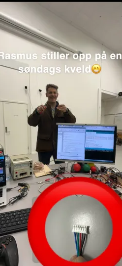
We have had an issue with connecting one of the steppers up properly for a while, as there are no available cables with connectors that fit. Normal female breadboard wires were just falling off, so we had to find a momentary solution while ordering the required cable. Hamsa was able to get in touch with Rasmus, who had access to the 3D-printer on campus. I gave him one of the connectors for reference, and so began a back-and-forth process of printing and shaping the printed piece to fit the stepper. This would have to be picked up again next week.

printed 6pin connector)
Hamsa Hashi 💻
This week, we worked on integrating the motor control for the robot using an Arduino Mega 2560 connected to the Raspberry Pi. By using the Arduino to control the stepper motors, we avoided challenges related to problematic libraries and dependencies on the Raspberry Pi. This decision also made it easier for Philip and me to collaborate, as we both have experience with C++.
To organize the work, we divided the task into steps.
Step 1: Control the robot with a game controller to verify that both the code and the stepper motors behaved as expected. This turned out to be more complex than expected, as we discovered that the stepper motors were not identical, something Philip mentioned earlier in the blog.
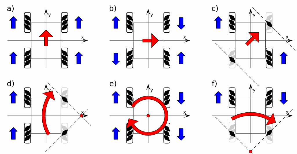
We connected the Arduino Mega 2560 to the Raspberry Pi via USB, using the same serial port in Python and Arduino IDE (installed on the Raspberry Pi) to test the motors. I connected the game controller to python through import pygame for controlling the motors, allowing us to check if the planned logic for omnidirectional mobility worked as intended. Due to missing components, as Philip described, we improvised by suspending the robot so the wheels could move freely without shifting the robot. This allowed us to observe how the motors responded to joystick input and whether the response matched the expected omni-directional movement without risking the robot rolling away.
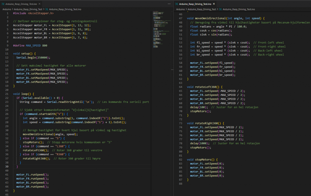
AccelStepper library. This code controls the NEMA 17 stepper motors without advanced features like Microstepping support, Smooth Start and Stop, Exact Angle Control, and fine-tuned Control of Direction and Speed. The motors are driven by simple speed calculations based on joystick input, lacking precise control for smoother and more accurate maneuvers.Along the way, we discovered that the last stepper motor had a different specification (single stack) than the others(double stack), which affected the joystick input as you can se in the video. A review of the datasheet showed that adjustments were needed. In the first version of the Arduino code, we had set the same speed for all wheels, but in the updated version, we adjusted the speed to 1000 steps per second per motor. This synchronized the movement better and eliminated issues with uneven acceleration that could cause the robot to move unpredictably.
To ensure the accuracy of the test results, we needed the last single stack motor de be running, so we contacted Rasmus, who helped us 3D-print a temporary 6-pin connector for the last stepper motor. This was a temporary solution, but it worked long enough to hopefully complete the necessary tests.


We also implemented controlled acceleration and deceleration to prevent jerky movements, which reduces stress on the motors and prevents steps from being lost during sudden load changes. Once the missing components are in place, we plan to implement microstepping for smoother movements, which will provide better control, reduce vibrations, and increase precision. We will also work on individual speed control for each motor to improve omnidirectional maneuvering.
Version 2 of python and Arduino code


AccelStepper for stepper motor management, ensuring precise control over speed and direction. The configuration supports Mecanum wheels, allowing smooth omnidirectional movement, while addressing step accuracy concerns with gradual speed adjustments.My plan for next week
I plan to run the code and perform real-time object detection locally on my Windows machine to improve performance. The goal is to use sockets to communicate between the Raspberry Pi and my local machine. By using sockets, I can send data from the Raspberry Pi to my Windows machine efficiently, allowing the Pi to focus solely on capturing video while my Windows machine handles the more demanding tasks of object detection. This should lead to faster processing and reduce latency+++.
Additionally, I will subscribe to the Raspberry Pi’s camera feed and stream it to my local machine. To make this setup work, I need to configure a router so that both the Raspberry Pi and my Windows machine are on the same network. I’ve decided to bypass the IKT system since it has been too limiting. See you next week 🙂
Ruben Henriksen 🛠️
DONE:
This week I came back from EuRoC and had to get back into my subjects. I began the redesign on the base for our robot. I checked out some materials we can use for our final product. For aesthetic reasons I am considering acrylic glass or some composite material.
TO BE DONE:
I need some more info regarding what sensors that need to be fitted, and I need to investigate some material properties to land on a final decision regarding the materials for our final product.
Kevin Paulsen 🛠️
What was done:
This week, I 3D printed the parts for the robotic arm, and then proceeded to assemble it like an engineer who finally found the perfect excuse to avoid homework. Most of the parts played nice and fit as expected, but a few decided to work against me and will need some corrections so that everything works as intended (and, you know, doesn’t break or refuse to fit together like a stubborn puzzle piece).
Next on the list: making sure the rebellious parts get sorted out, so the final version doesn’t just look cool but works like a charm too!
Here is a picture of the 3D printed model next to the SolidWorks design, just to prove it’s not all happening in my imagination.
Sokaina Cherkane 💻
This week, I collaborated with Mikolaj to set up the necessary software and hardware for controlling a robotic arm. We installed Dynamixel Wizard 2.0 and R+ Manager, software tools specifically designed for configuring and managing Dynamixel actuators—a type of advanced servo motor widely used in robotics applications like robotic arms. For the hardware setup, we installed four servo motors (shown in the image below) to enable full rotational and linear movements. We connected the first servo (S0) to an OpenCM_9.04 (check the picture below) and successfully tested the arm’s range of motion, including 360-degree rotation, forward, upward, and downward movements.
Towards the end of the week, I began studying forward and inverse kinematics, essential concepts for precise robotic movement. Forward kinematics allows the calculation of the arm’s endpoint based on known joint angles and link lengths, ensuring accuracy in reaching a specified location. In contrast, inverse kinematics determines the necessary joint angles to reach a specific point in space, it is critical for picking up objects at exact positions. Together, these techniques ensure predictable and precise movements.
Additionally, I started learning about ROS (Robot Operating System), which is advantageous for a robotic arm as it provides a framework with pre-built libraries for handling complex movement control, sensor integration, and efficient development.
Mikolaj Szczeblewski 🔋
What was done:
This week I have managed to get the servos to finally have a code compiled through the Arduino IDE which made them run.
For any students stumbling upon these servos, one important thing you have to know (Yes, very dumb thing to mention, yet it is easy to forget):
– The Dynamixel Wizard 2.0, which is a program for configuration, testing and firmware updates for the Dynamixel Servos, establishes a serial connection through a USB port, the same port which also communicates with the Arduino IDE, only one program can access the serial port at a time.
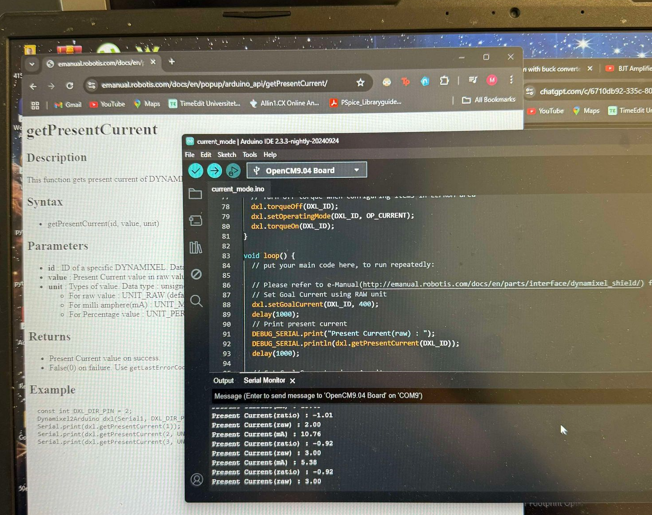
Therefore, the code was correct, but it couldn’t compile through because of this reason. I didn’t consider this to be a problem earlier, as I thought it was a program that had some kind of “real-time control” or monitoring application and demanded to maintain constant uninterrupted communication , however that was not the case.
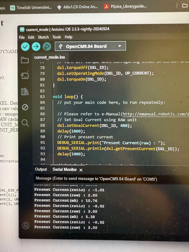
With Steven’s help we’ve managed to establish this communication, however the whole system will be controlled by the brain which is Raspberry Pi, and for our Computer engineers’ wish, we have to implement a python API for this purpose, given that all other hardware will be communicating only through that particular language.
I have ran sketches provided by the Dynamixel2Arduino library, where I tested the velocity and position control of the servos, and also the current measurement in mA.
Since I have the most expertise on the servos and the control tables that address every operation that a Dynamixel servo is dependent on, I will have to guide the Computer engineers through the correct calibrations and code adjustments to the servos, so that we are not at risk of harming the hardware.
The testing will no doubt be excruciatingly time-consuming and difficult to comprehend at first glance, in terms of programming the servos. Nevertheless, when we finally establish the communication with the Python API, the computer engineers will have the opportunity to test the servos and program every “joint” accordingly.
Already this week we’ve looked on the DynamixelSDK, a software development kit for controlling Dynamixel servo functions using packet communication.