Welcome to the combined sixth and seventh ToyzRgone project blog!
Due to a large portion of the team is focusing on resit exams and balancing commitments to other courses, we decided to merge these two weekly updates into one. We’ve made steady progress toward our goal of building a fully functional self-driving robot. Below, you’ll find the key highlights from our recent work and the steps we’ve taken to keep moving forward.
Hamsa Hashi 💻
What Was Done
The past two weeks, despite exam preparations, Sokaina and I focused on improving the dataset and fine-tuning the model. Last week’s testing showed the need for more varied images to distinguish target objects from other round objects. Therefore, we expanded the dataset and set up a new testing process for more accurate evaluation.

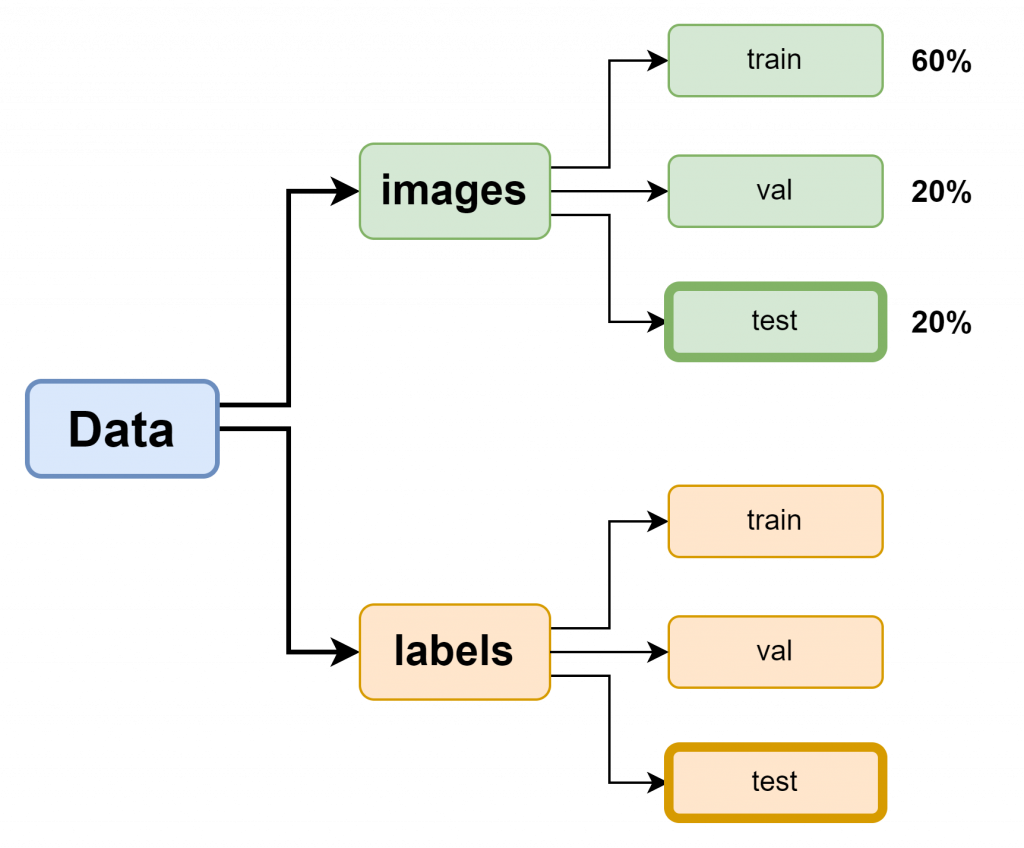
The previous dataset and file structure only included training(train) and validation(val) sets, which limited the model’s ability to properly test whether it had genuinely “learned” throughout the epochs. To address this, I have now added a test set with images, following best practices for creating a custom dataset based on the documentation. This adjustment will allow for a more accurate assessment of the model’s performance on unseen data.
Sokaina and I took additional pictures of the blue, red, and green balls in realistic environments, using a Python script she created that connects her phone to Google Drive for automatic uploads. Great job from Sokaina! both efficient and a real time-saver, in my opinion. We also added images of other round objects to train the model to ignore them. A separate test set was created with images not included in the training set to ensure the model is truly learning to recognize objects.
Fine-Tuning Training Parameters
# Tren YOLOv8-modellen med optimaliserte parametere
results = model.train(
    data=os.path.join('/content/drive/MyDrive/ComputerVisionEngineer/ObjectDetectionYolov8GoogleColab', "google_colab_config.yaml"),
    epochs=50, imgsz=640, lr0=0.01, momentum=0.937, weight_decay=0.0005, augment=True, save_dir=train_results_dir
)
Before the new training, We reviewed Ultralytics documentation and adjusted parameters to better balance accuracy and performance. The image size was set to imgsz=640, with a learning rate of lr0=0.01 and momentum=0.937 for smoother training. To prevent overfitting, I used weight_decay=0.0005, and enabled augment=True to make the model more robust.
Challenges with Testing and Hardware
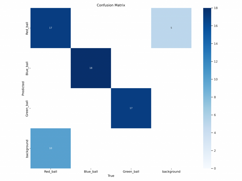
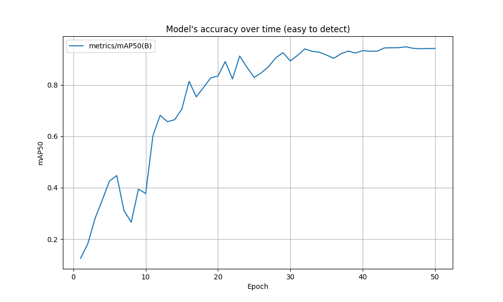
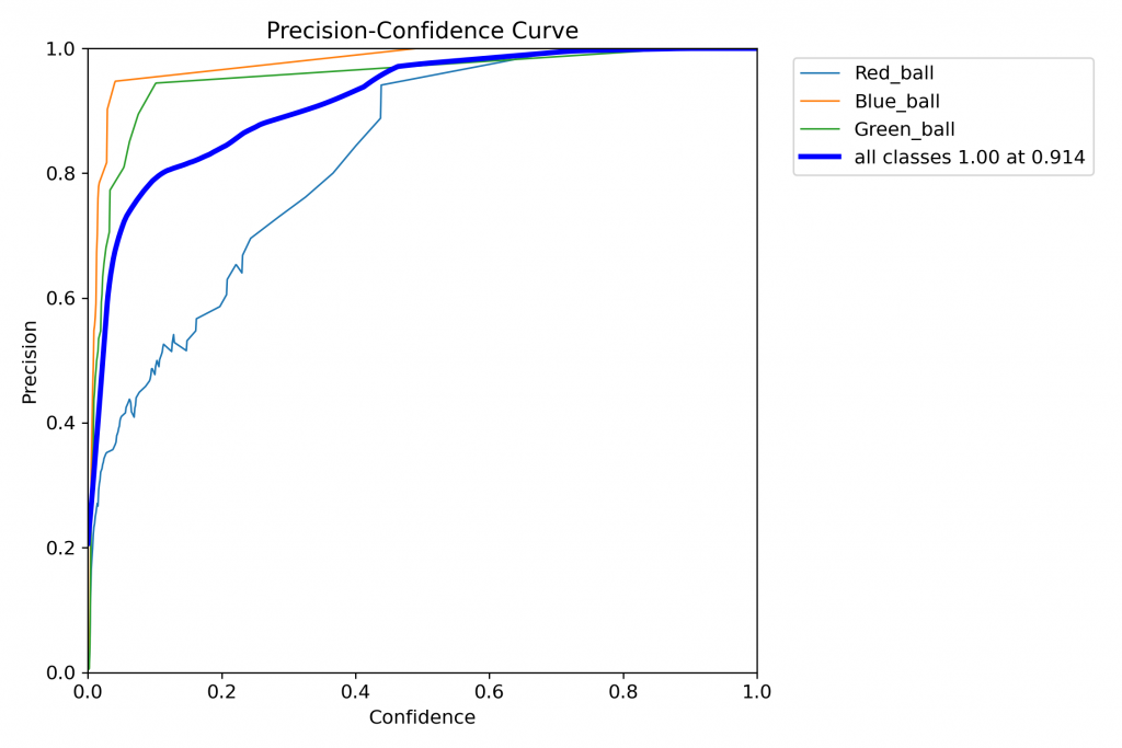
Despite improvements, we think the model still struggled with precision under poor lighting, and the mAP results were not fully satisfactory. The Raspberry Pi 4 also faced performance issues with real-time detection, and camera stream delays made testing challenging. As a result, I moved development to my Windows machine, which offers better hardware performance for real-time detection and model testing.


Moving forward, I plan to handle the more complex tasks, such as object detection, on my Windows machine to bypass the Raspberry Pi’s limitations. I will subscribe to the camera feed from the Raspberry Pi, ensuring we don’t compromise performance while still using the Pi’s camera capabilities.
Next week
In the coming week, I will also begin working on the robot’s movement system together with Philip. We will start by researching NEMA 17 stepper motors and how they can be integrated with the camera system. To begin, I’ll use a game controller to test the basic functionality and ensure everything works as expected. Once confirmed, the stepper motors will receive movement commands based on the camera’s x/y coordinates. The long-term goal is to integrate LiDAR with ROS to enable SLAM (Simultaneous Localization and Mapping), allowing us to capture x, y, and z coordinates for objects the robot needs to pick up.
Sokaina Cherkane 💻
NB. Exams on both week 5 and 6.
To be more productive, Hamsa and I agreed to work on different datasets. I will train the one that I made from scratch on VS Code. Meanwhile, he will train an imported one from Roboflow directly to the Raspberrypie.
Both of us met some errors and challenges, where the dataset wasn’t well trained. (check the pictures below)

The program is not precise since it mixes different colors. 1 is meant to be red, 2 is blue and 4 is green. But the program is still inaccurate. Plus, the camera on the RP couldn’t distinguish a human from a ball. We came to the conclusion that we must combine both his and my dataset, re-train it, and test it directly on the RP.
Uke 7.

After almost nine hours of code debugging on the RPI and dataset adjustments, I could finally get the RPI camera to be read directly, displaying the results on the screen as shown in the videos below.
Hamsa and I decided then to collaborate in order to achieve a more accurate and detailed data recognition, we arrived at the following results (see image).
The day started off by making a new dataset, the pictures were taken at both our grouperoom and Dronesonen, to expose the balls to different lightning, we also made sure to include human faces to assist our program to distinguish between balls, people and other individuals/objects. Next we filtered the pictures, annotated them and started the training process.


We tested the dataset with a standard external camera, which was very successful. Afterward, we tested it with the Raspberry Pi’s camera, where we could observe differences and improvements in our final dataset, a combination of two custom datasets and one imported from Roboflow. Now that the dataset is more precise and accurate, it’s usable, and we are ready for the next step.
Next week:
Hamsa will be in charge of the car, and I will handle the robotic arm. I plan to dedicate next week to learning forward and inverse kinematics after testing the arm using OpenCM 9.04. It has not yet been decided if I will use ROS or not.
Philip Dahl 🔋
Converter
This week I looked into options for powering the microcontroller(s). Although a power supply/battery pack has not been officially determined yet, we are likely using a 12 V source. The microcontroller needs 3.3V-5V(depending on what controller we use), so we need a converter.
I had previously designed a 12V to 5V converter in OrCad Capture in the Electronic Circuits course which I used to simulate output results.
Picture to the Left: The signal reached 5V at around .5 ms and oscillated between 5 and 5.2 V. This would probably be good enough, but I wanted to see if the rise and peak time could be shortened as well as get a stable value closer to 5.0 V.
To get a lower overshoot value, the circuit needed higher damping. To the Right ^12 V power source and 12 to 5 V converter using LM3478.
Nema 17 Stepper Motors
As the base for our robot was assembled with the steppers, I connected them to the drivers on a shared breadboard. This was a temporary, but more complete solution and was mostly so that we could run tests that more closely resembled the final product. I tested the steppers again now that they were mounted, just to be sure that they were still functioning.
I am only missing one driver and some wires to have all steppers up and running simultaneously, but this is a quick fix as soon as they are in my possession.
Mikolaj Szczeblewski 🔋
What was done:
This week I’ve done more research on the Dynamixel relevant software, aside from the Dynamixel wizard 2.0 which is a crucial program for scanning both the OpenCM 9.04 board aswell as the servos. It is not “the” program which helped me in installing the firmware needed for both the servos and the board. That was the R+ manager.
R+ manager (Roboplus manager 2.0) is a program that is a “must have” when using the OpenCM 9.04 board. This program enables you to update Dynamixel products to their latest version. If we don’t have the firmware installed to the newest version, then the Dynamixel wizard 2.0 won’t detect the communication protocol from both the OpenCM and servos. Therefore I have updated both the OpenCM 9.04 and the XM430-W210-T Servos to their newest version.
Now you might ask, why don’t I do it through the Dynamixel Wizard 2.0? It sounds like a program that should have also have the same firmware recovery feature?
Indeed it has, however OpenCM 9.04 is quite the outdated board, and Dynamixel Wizard 2.0 is not supporting a firmware recovery for that board any longer. (A variety of products from Dynamixel are discontinued which date to 8 years back)
The reason why this is important to note is that I have ran example codes which didn’t do anything, despite going through the compiler. However as a result, the firmware would be “erased” quite literally.
A lot of time has gone into this and this has given me insight into how we can prepare ourselves for the final testing phase, and how we will be able to identify potential communication failures involved with the servos.
Kevin Paulsen 🛠️
What was done:
This week, I made some improvements to the robotic arm. First, I designed and added a mounting plate on top of the arm to securely attach the camera.
I also worked on compressing the base of the arm further, successfully reducing unnecessary size and weight. Along with that, I added more fastening holes for screws and bolts to assemble different components inside the gripper.
Although these improvements are coming along well, there are still a few areas that feel a little unclear, particularly around the gripper base and fastening, which will need more fine-tuning in the next iteration to ensure everything works smoothly
Ruben Henriksen 🛠️
DONE:
This week I assembled the prototype of the base so the electronics and computer engineers would have something to work on. I redesigned the adapters for the motor and wheels and set them to print. I then traveled to Portugal to attend the European Rocketry Challenge and was unable to work too much on the project during this time.
TO BE DONE:
I will continue the design of the base of our robot and perform some further analysis.