Welcome to the fifth installment of our ToyzRgone project blog! We’ve been working hard for yet another week, getting one step closer to our goal of developing a fully functional self-driving robot. Below, you’ll find the highlights of our progress and the individual contributions made this week.
Kevin Paulsen 🛠️
What was done:
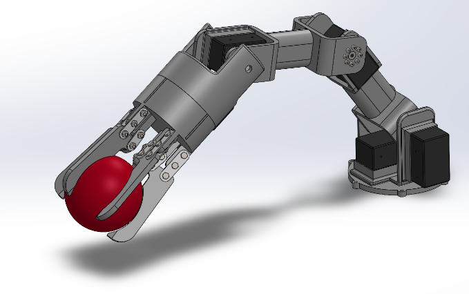
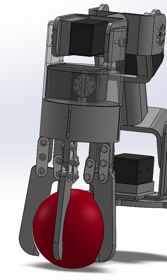
This week, I added the material we plan to use, Nylon 12 SLS, to the SolidWorks model. Since this exact material wasn’t available in SolidWorks, I had to create a custom material using parameters provided by Ruben, who had tested it. I also set the weight of the Dynamixel servos to their exact weight, which is 82 grams, and included the weight of the ball we’ll be picking up, which is 350 grams. This will help us later when calculating the center of mass and the moment forces for the arm.
I made adjustments to the gripper as well. Now, when the servo turns 180 degrees to fully close the claws, it will have a perfectly tight grip on the ball it needs to pick up. I also split the gripper base into more separate parts because it was originally a single piece with moving parts inside, making it impossible to assemble in real life. This issue is now resolved.
Lastly, I attached the gripper to the rest of the arm, but the base and fastening still need a few adjustments to be fully complete.
Hamsa Hashi 💻
What was done:
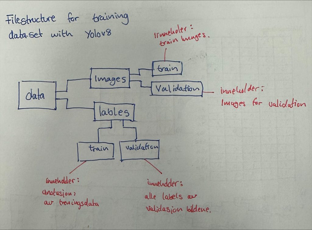
This week, I worked on trying to finalize the dataset and annotating images to meet YOLOv8’s structure requirements. In YOLOv8, a YAML file defines datasets, specifying paths for training, validation, and testing, along with class names. I selected 158 images of blue, red, and green balls to test if this amount is sufficient to train a custom best.pt model capable of detecting our target objects. The images are organized in a folder structure according to YOLO’s guidelines, and I’ve attached an image of this structure for reference. Next, I’ll assess the model’s initial performance and make adjustments as necessary.
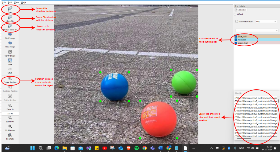
Each annotated image in YOLOv8 also requires a corresponding .txt file. This .txt file includes critical information for each object detected in an image, such as the class label (01 for Red_ball, 02 for Blue_ball and 03 for Green_ball), bounding box coordinates, and relative location of the bounding box to the object. This file setup ensures YOLO has precise data for effective object detection training.
To streamline annotation, I developed a small user interface using the Qt5 package, part of the Qt framework, which combines a Python backend with a responsive QML-based frontend. The interface allows the program to access two folders: one for images and an initially empty folder where Pics.txt files are saved. As images are processed, this folder fills with .txt files containing object type, bounding box coordinates, and position. This setup aligns with YOLOv8’s structure and simplifies future updates if additional images are needed to improve model accuracy.
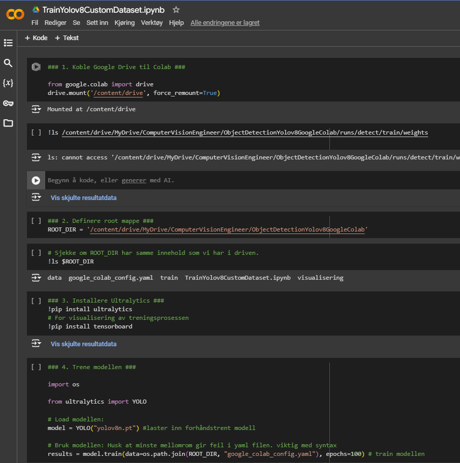
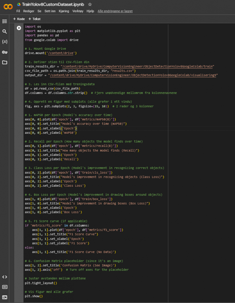
In Google Colab, I set up the environment to train my YOLOv8 model on the dataset of colored balls (red, green, and blue). I mounted Google Drive for data access, installed the ultralytics library for YOLOv8, and configured training parameters like batch size and epochs. During training, I monitored key metrics—accuracy, precision, loss, and F1 score—through generated graphs, including a confusion matrix and mAP plot, to assess model performance. Using Colab’s GPU support significantly accelerated the process, allowing me to optimize and evaluate the model efficiently.
Over to the (funny/not funny) part
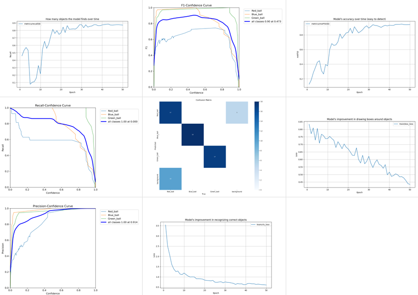
After training the images and visualizing the results, I felt satisfied with the outcome—at least initially. However, that feeling didn’t last long, and I’ll explain why soon. Here are a few images illustrating the training results. What do you think? Doesn’t it look good?
The next step was to set up the code to run the custom-trained model (best.pt) in Python on the Raspberry Pi 4 camera module and actually test whether the dataset performs as expected. It wasn’t until I ran the code that the answer became clear: the dataset needs more training, and many more images must be added that expose the model to the same environment in which the camera will operate. The training data seems capable of detecting the objects in the provided images but struggles to differentiate between other round objects it hasn’t seen before. Here is an example of the model’s current abilities.
so next up:
I’ll focus on adding a test set to accompany the validation and training sets. This test set will contain some images to help verify if the model is genuinely learning to detect objects, rather than simply memorizing the specific images in the training set and using that to predict which ball it is. This will ensure that the model is actually training in the way we intend.
Additionally, I plan to take more photos of the environment that the camera will be exposed to, increasing the model’s exposure to real-world conditions to improve detection accuracy. I’ll monitor how long this additional training takes and adjust as necessary.
Thanks for following along—see you next week!
Philip Dahl 🔋
This week mostly went to preparation for a cont. exam next week. This had a slight impact on the amount of work I got done but rest assured, I will return to the regularly scheduled work after the exam.
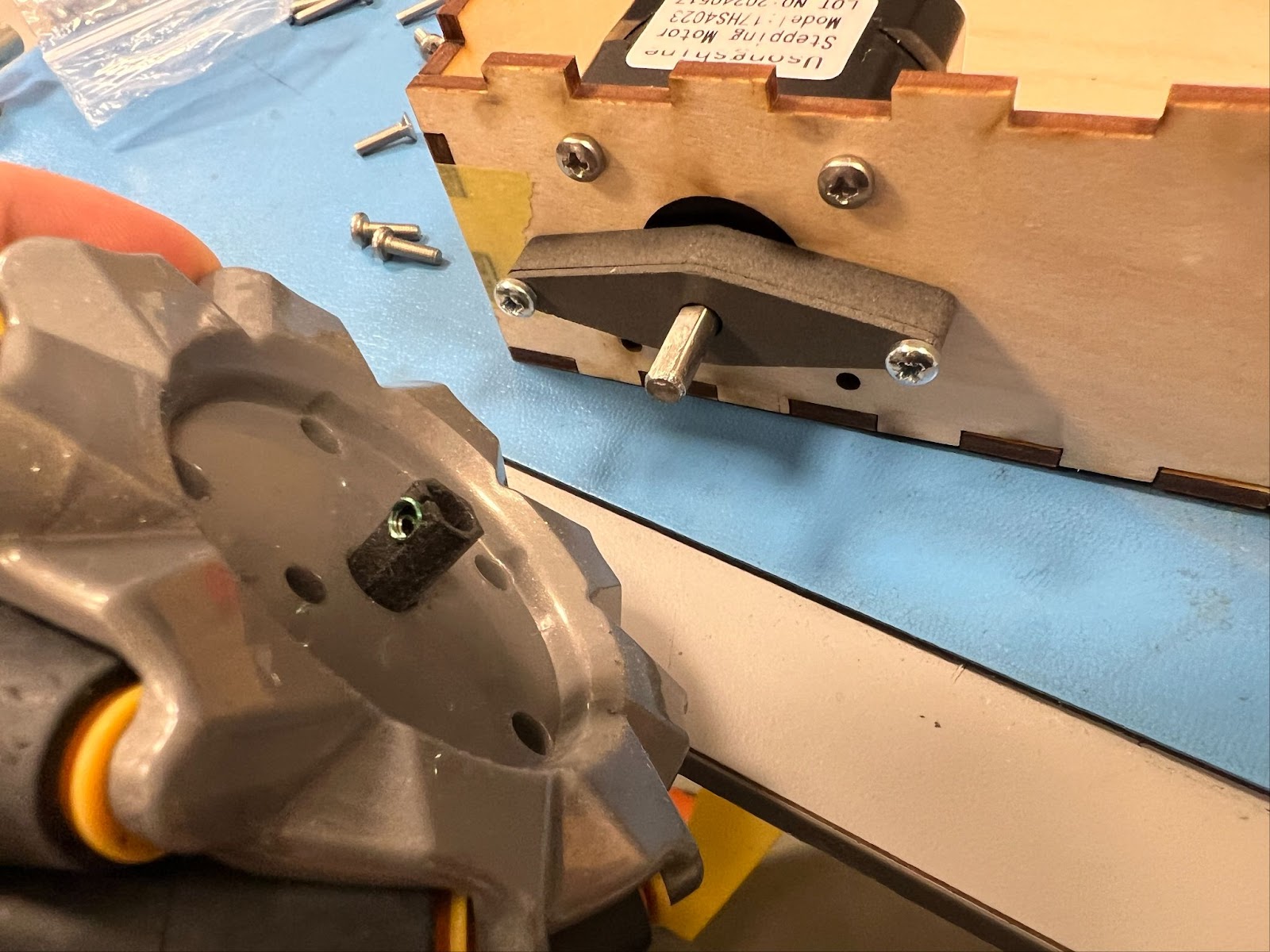
Motor Control
To start this week off I wanted to check the rest of the NEMA17 steppers we had on hand to see if they were functional. I knew that at least one of the steppers worked fine after last week’s testing and that one might be faulty. I knew that the two coils inside the motor had two wires each that would have to be paired together for the motor to properly run.
With the possibly faulty stepper I tried changing the pairing until the motor worked. I figured that this model of NEMA17 had different pairing than the other models and would be why it had previously seemed faulty.
Mikolaj Szczeblewski 🔋
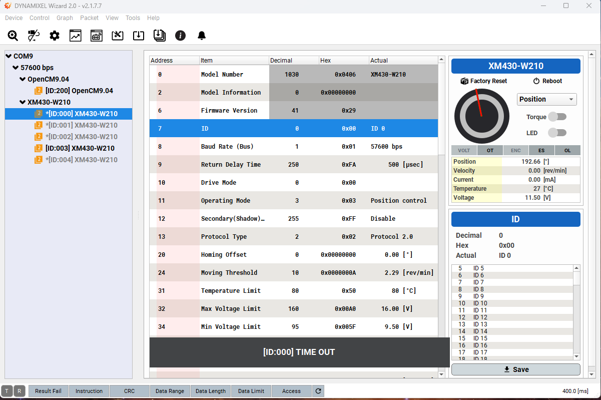
This week, my priority was to calibrate the servos and download the necessary firmware and drivers to make the OpenCM board actually communicate with the PC. This was done on my private PC, however eventually we will be implementing this into the raspberry pi.
I’ve downloaded the dynamixel wizard 2.0, which is a software meant for maintaining communication between the software and the dynamixel servos at all times, as long as the software is opened on the PC. With this program, I can manually enable the torque on them which deactivates the blockade on them. In addition I can also turn on the LEDs on them, which may be beneficial later on so that we could troubleshoot the daisy chained servos and find out which one is malfunctioning in terms of communication failure or not enough current input.
Underneath the calibration I stumbled upon some problems, the servos had overlapping ID’s, which is not ideal, because, the servos depend on their own unique ID to work in a daisy chain connection. If we have overlapping ID’s, a communication failure will occur and the dynamixel wizard will not be able to identify the servos.
The servos I’ve daisy chained have been marked with sticker notes by ID numbers, so that we have a system to follow and may connect them in the exact order.
And of course, the servos actually work, which is exciting. I can turn them around 90 degrees and -90 degrees. The most interesting part is that the servos do not rotate based on degree values, but based on raw position integers, these vary from 0 to 4095, (4096 being just 0 / 360 degrees). This allows for much greater precision and finer control over the servo’s position, however this makes sense why they are so precise, they have built in encoders and a closed loop feedback system which constantly tracks the rotation in small increments.
And now for the upcoming week, we are preparing a presentation for this project, we are excited to show it!
See you next week!
Sokaina Cherkane 💻
NB. Exams on both week 5 and 6.
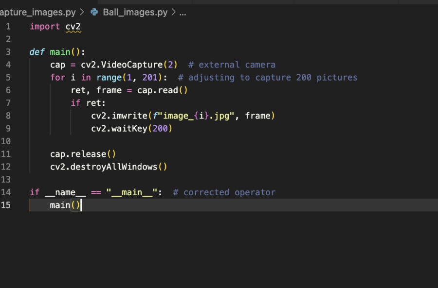
During this week I was not able to work on the project due to the exam (konte-uken). Therefore I dedicated most of my time to exam preparation. However, I managed to write a python code that will be able to take several pictures (about 200) every 5000ms from different angles in order to make a dataset from scratch. This will provide a better data quality, and will make it more relevant to our project. This will assist our camera to recognize the targeted balls.
next up:
The plan next week (week 6) was to filter the good pictures from the bad ones and then train them on VS code.
Ruben Henriksen 🛠️
This week, we acquired some larger wheels to solve our height issue. I designed an adapter to attach the wheels to the stepper motors, but the wheels sat too far out on the axle due to an attachment screw in the wheels. To fix this, I built a bearing holder to support the axle and reduce stress on the motor, transferring the load to the chassis.
Both the adapter and bearing housing were made from Nylon 12 using an SLS printer. I added metal Helicoil threads to the bearing holder because plastic threads wear out quickly with repeated use, making it more durable. This will help in the future with maintainability.
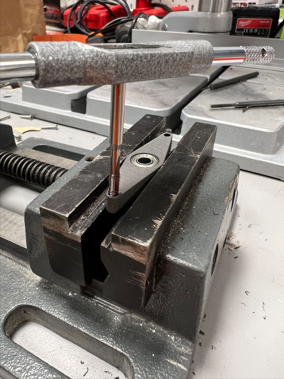
The Images shows the installation of the Helicoils. I printed holes in the part but drilled them larger and tapped the plastic, I then screwed the metal threads to install them into the part. I also tried to add Helicoils to the adapter but the walls were too thin and needs a redesign.
Next week, I’ll assemble the base prototype so that the data and electronics engineers can begin their testing. I will continue my work on the base, and I will design something to mount the Lidar scanner that the electronics guys are considering using.