Welcome to our blog post for the third week of our ToyzRgone system project. Below, you will find the contributions made by each of our team members:
Hamsa Hashi & Sokaina Cherkane 💻
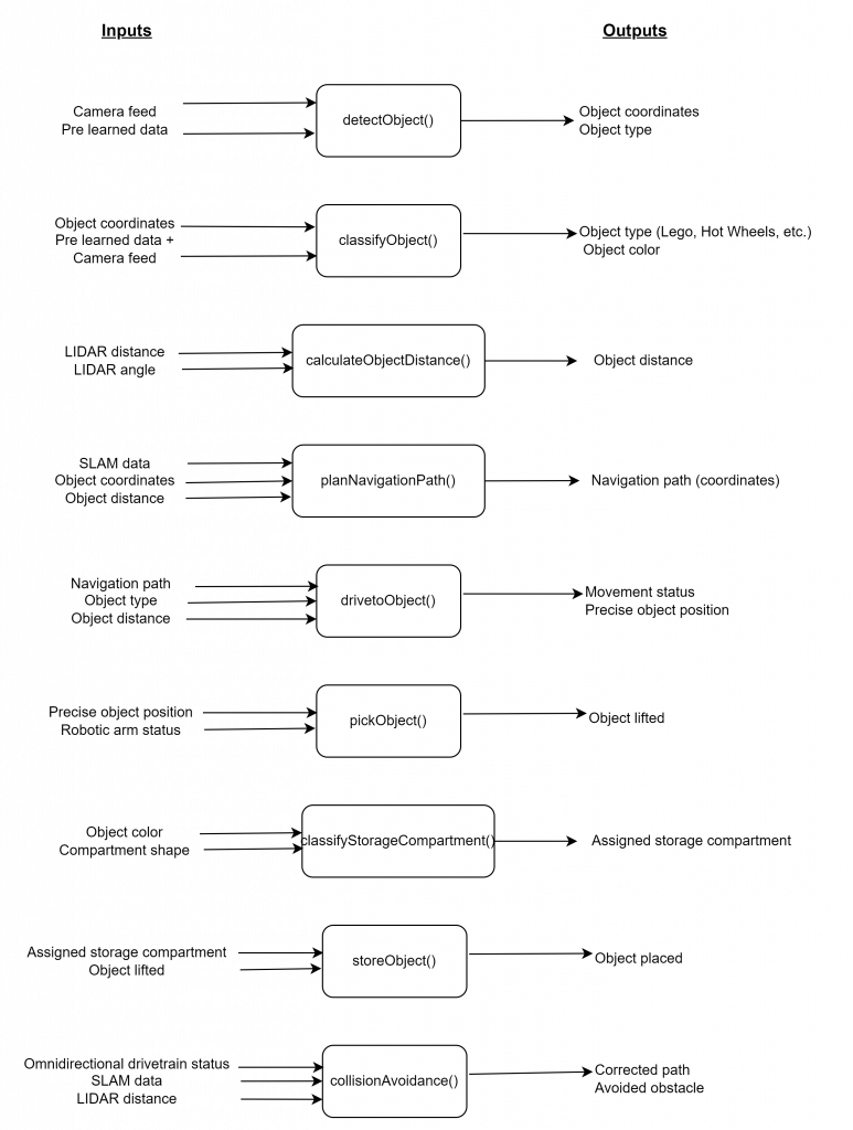
Diagrams outlining the inputs and outputs for the key system functions in a black-box format.
Given that our group’s tasks are split among individuals and disciplinary teams, Hamsa and Sokaina developed basic black-box diagrams to outline the key inputs and outputs for the main system functionalities. The aim is to facilitate the early stages of implementing and testing software functions that will later integrate with electrical or mechanical components, including training the YOLO model and object detection:
Throughout the week, we have been working to explore OpenCV, Tensorflow, HAAR Cascade, and YOLO in Python for color and object recognition. We dedicated our time on understanding the basics of image processing and neural networks (incase we will use it) through hands-on experiments using Jupyter Notebook. We worked with the MNIST dataset, a collection of handwritten digits, to practice image recognition.
The key steps we focused on included:
- Loading and Visualizing Data: We loaded the MNIST dataset and visualized digit samples as 28×28 pixel matrices using matplotlib. This helped me understand how computers interpret visual information.
- Preprocessing the Data: We also reshaped and normalized the data to prepare it for neural network training, ensuring efficient processing and faster convergence.
- Building and Training a Neural Network: We built a simple neural network using Keras and TensorFlow, experimenting with batch size and learning rate to improve accuracy.
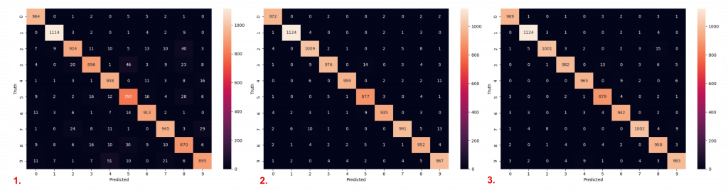
- Evaluating Model Performance: We tracked accuracy and used confusion matrices to assess the model’s classification performance and identify areas for improvement.
This hands-on work gave us valuable experience in image recognition, particularly in detecting and classifying objects based on visual characteristics. These skills are directly applicable to the ToyzRgone project, where image recognition is key for detecting and sorting toys by shape and color. This week deepened our understanding of neural networks and their application in image recognition tasks, preparing us for future project developments.
Methods choosen for object detection
Haar-cascade vs YOLO:
We choose to explore YOLO over Haar-cascade for object detection based on its superior efficiency and accuracy, particularly in real-time applications. As documented in a comparative study:
“The model trained using the YOLOv3 algorithm has high accuracy; hence, the Neural network-based YOLOv3 technique is thought to be the best and most efficient”
https://www.diva-portal.org/smash/get/diva2:1707864/FULLTEXT02.pdf
YOLO’s ability to detect multiple objects simultaneously and its fast-processing speed make it ideal for resource-limited systems like the Raspberry Pi, where performance is crucial. Haar-cascade, while simpler, does not match YOLO’s precision or speed in complex tasks.
Looking ahead:
Next week, Sokaina and Hamsa plan to collaborate on researching, locating, or creating a dataset if needed, to train the YOLO model for object recognition. We will also test our code on a Raspberry Pi camera. See you next week.
Philip Dahl & Mikolaj Szczeblewski 🔋
This week we’ve began looking for components that might suit the functions of the system for which our project is based upon.
The electrical engineers researched this week the types of DC-motors and servos that could be realistic for a robotic arm. It was much easier to settle upon what to use for the mecanum wheels. However for the robotic arm this will be a more complex decision, given that we’d ideally want the robotic arm to be able to lift slightly larger objects, and of course, for it to have a solid grip, for that we need strong servos.
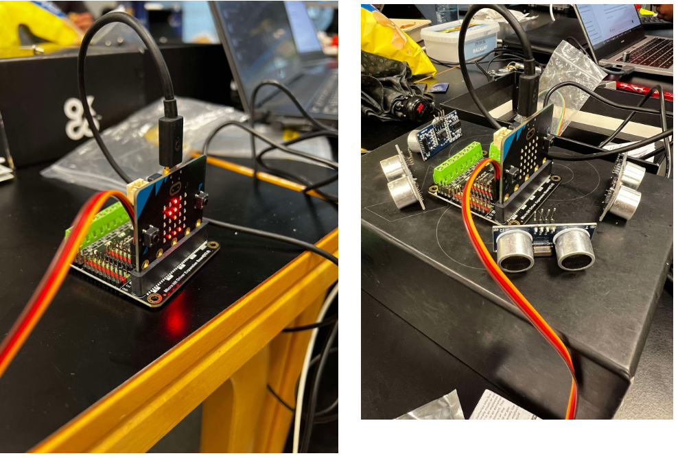
The expansion board, DFR0548, which is manufactured by DFRobot, is a Micro:bit compatible, driver expansion board. It consists of 4-way motor drives, 8 servo interfaces. This will be connected to a micro:bit (microcontroller), which the computer science students will be providing the code for.
We’ve also obtained ultrasonic sensors, 4 of them to be precise. Their objective will be to hinder any collision. The principle of this component is quite simple, it will send an ultrasonic pulse at 40kHz (roughly), this will travel through the air, if it hits an object, the pulse will bounce back to the sensor. The calculation of the travel time and the speed of sound determines the distance, and in that principle the sensor can be aware of its surroundings.
In terms of power distribution, the expansion board does not consume a lot of power, in fact, 3.5 to 5.5V, yet the servos we have considered using are at a recommended 12V. For this we will have to adapt and consider what we will be doing next. DC-DC converters, regulators, these things will be discussed at the next meeting to assess how to connect the servos with the expansion board however at separate voltages.
The reason behind why we’d like to use bigger servos is not only for the challenge, but also to give a little more playroom for the mechanical engineers to experiment with.
https://no.mouser.com/new/dfrobot/dfrobot-dfr0548-microbit-board/
https://support.microbit.org/support/solutions/articles/19000013983-what-is-a-micro-bit-
Kevin Paulsen 🛠️
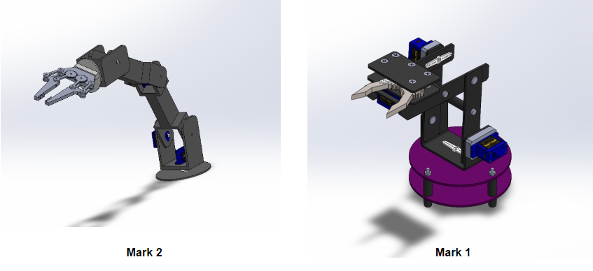
This week, I created the first draft of our robot arm (Mark 1) by following and replicating instructions from two YouTube videos: Design a Robot Arm Use Solidworks and Design a Gripper Use Solidworks. This was primarily for inspiration and to gain a better understanding of how a robot arm can be designed and assembled.
Afterward, I moved on to developing the next version, the Mark 2 robot arm, based on a more agile and flexible model that Ruben obtained for us. As shown in the images, the Mark 2 features more joints and servos compared to the Mark 1, with 6 servos instead of 4. The additional joints make it longer and more maneuverable. Starting from the base, it can rotate 360 degrees, and the next 3 servos control each arm segment in the y-axis, improving angular accessibility. The last 2 servos manage the head and gripper, allowing 360-degree rotation as well as the opening and closing of the gripping mechanism.
Ruben Henriksen 🛠️
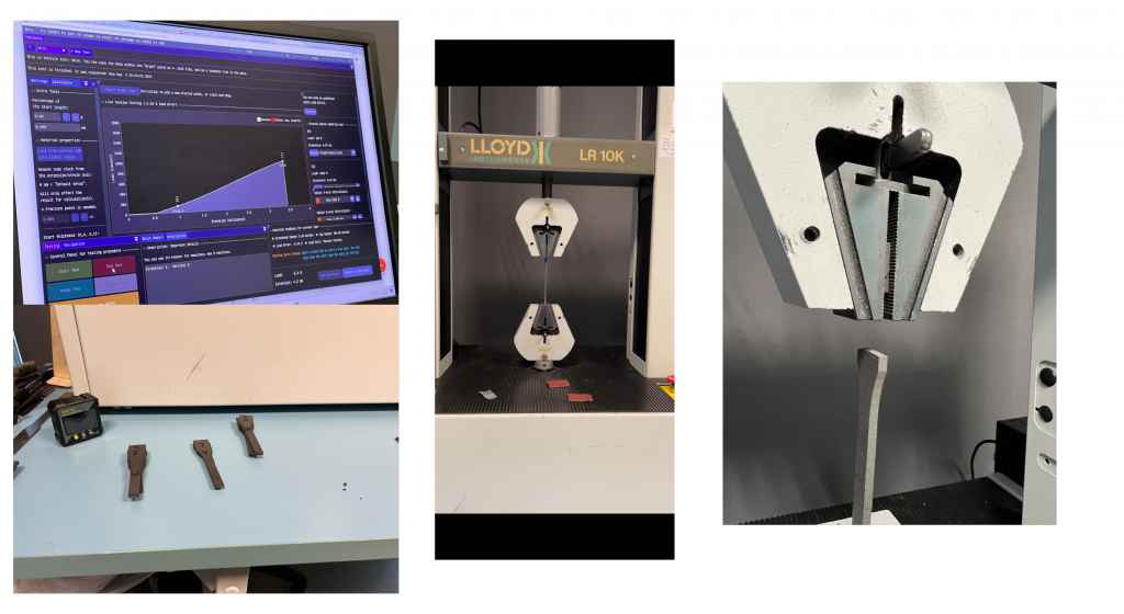
This week I have investigated the possibility of using an SLS 3D printer to manufacture components for our robot. The printer uses Nylon 12 as a material so I have created test rods in accordance with ISO 527-2 1A. I have then performed tensile tests using the Lloyd LR 10k. The tests indicate an Ultimate Tensile Strength (UTS) of about 38,7 MPa and a Tensile Modulus (E-Modulus) of 1424,2 MPa. This is slightly lower than the datasheet which indicated a UTS of 50 MPa and an E-modulus of 1850 MPa.
Regardless these results are useful since we intend on doing some topology optimization for some of our parts and accurate materials data are needed for the simulations.