Enjoy the Hydroplant demo
Documentation for all our code and links are now available here:
Shahin Ostadahmadi
- This week i have been testing the system over and over again. I have also tested nutrition controller and was able to detect most of the bugs. The software follows correct logic, but the test could not be finalized be cause of the valves; they do not open enough to get enough water flow, and this is problem because we have 3 reservoirs and we have to be able to correctly route the water flow. The new valves have arrived and we have to buy some connectors next week.
- Implemented some new pages on GUI for future development with fictional data
- Updated doxygen documentation for all the system parts i have worked with.
- Updated the website to host all the documentations and GitHub links for our repositories.
- Sat up the project room ready for demonstration with the team.
Since it is last week, i would like to summerize what i have worked with during the semester.
Development
1
GUI
Responsible for an interface to control the system manually through a graphical user interface. You can control actuators, logic controllers, see logging from the system, picture from plant scanner, and much more!

2
Micro controller library
The main Hydroplant library with built in communication protocols, task management, base classes for logic controllers and other classes for actuators and sensors.
3
Snap-on-command
Provides interface for taking picture, analyze pixels and send back the information to the commander. It provides also a page for streaming live video feed. It can also do both at the same time.
4
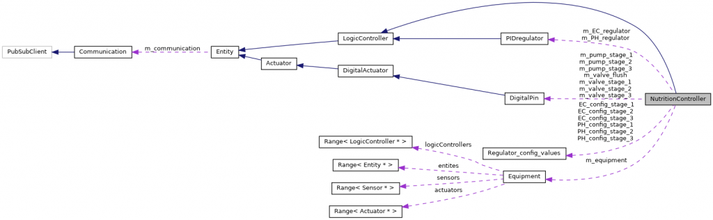
Nutrition controller
A centralized regulation box for regulating nutrition and pH level for all the stages in one place. It regulating each stage at a time and ensures to log each log data for each stage when regulating.
Hydroplant
Hydroplant Library
Introduction
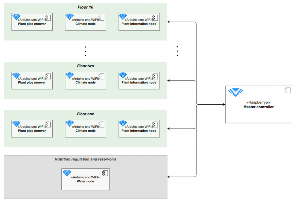
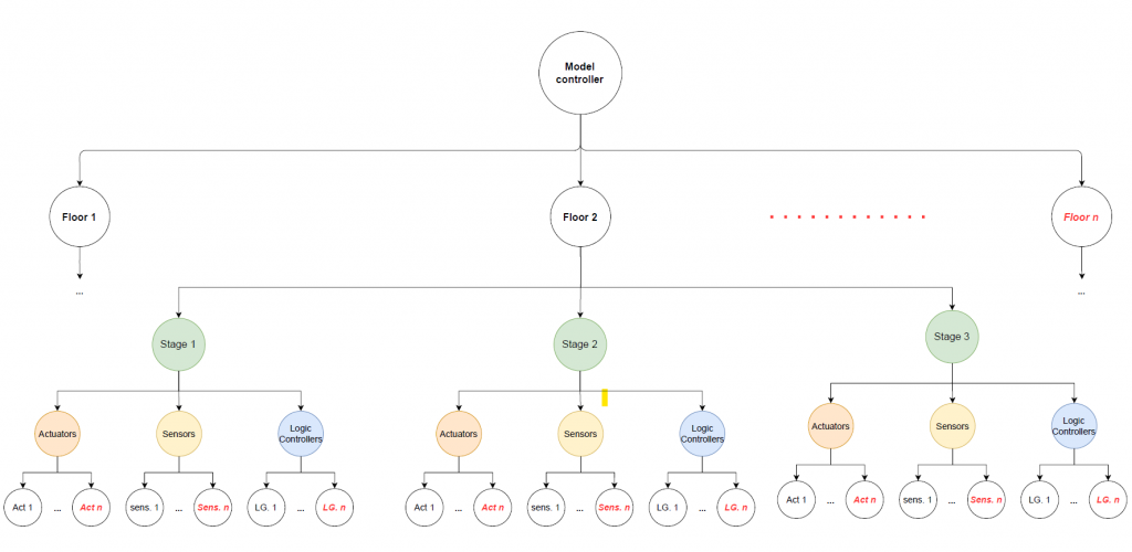
The library offers tools for building scalable vertical farming systems, focusing on multiple floors. Key components include:
- Nodes: These are user-defined logic controllers like the Nutrition Controller, Plant Mover, and Plant Information Node.
- Core Functionalities: These include sensor reading (logging measurements at intervals), a PID regulator (maintaining target values with sensors and actuators), and defining actuators’ actions.
- Communication: The library uses MQTT for communication within the network. It allows devices to connect with a Master Controller, providing details about sensors, actuators, and logic controllers. Each entity gets dynamic addresses for commands, logs, and receipts.
- CommunicationHandler: This class handles entity initialization, network and MQTT setup, topic creation, and task management (like queuing and processing commands). It ensures continuous connectivity with the network and MQTT Broker.
Use cases
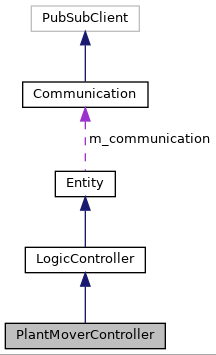
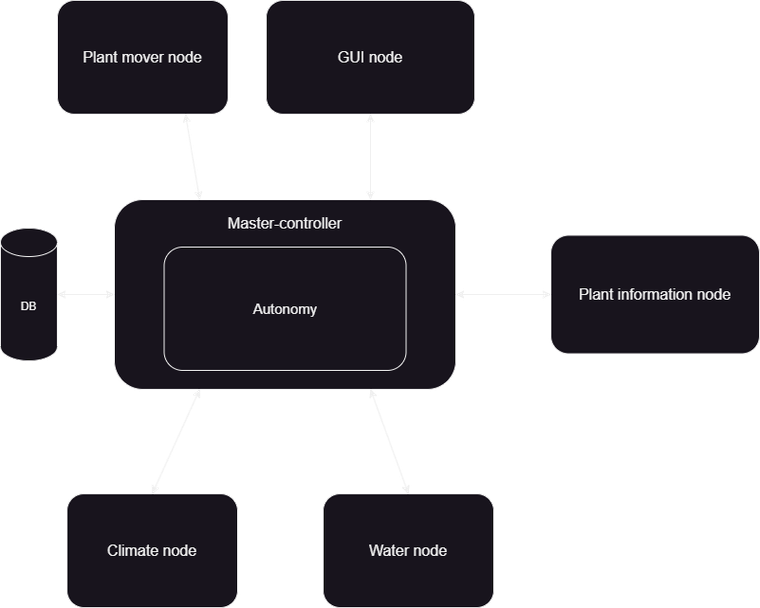
In the diagram bellow you can see how the Nutrition Controller uses the Library functionalities for nutrition regulation.
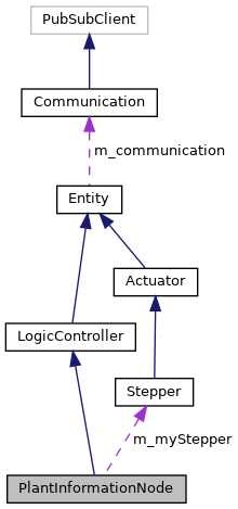
How Plant mover and information node uses the library
Hydroplant
GUI
Features
The application is designed using the Model-View-Controller (MVC) pattern. It includes a custom container that manages information about the system. This container dynamically creates and removes objects based on information from Master Controller. Additionally, this setup ensures that the state and information of objects are kept consistent and synchronized with the physical system.
The front-end uses this information to create visual elements for the user.
All pages on GUI
The pages on Left, right and top is static, while the page in the middle is a swipe view where you can swipe between different pages. The log section is connected to the system and any node can log with different levels (INFO, WARNING; and ERROR). The GUI will also show different colors based on log level.
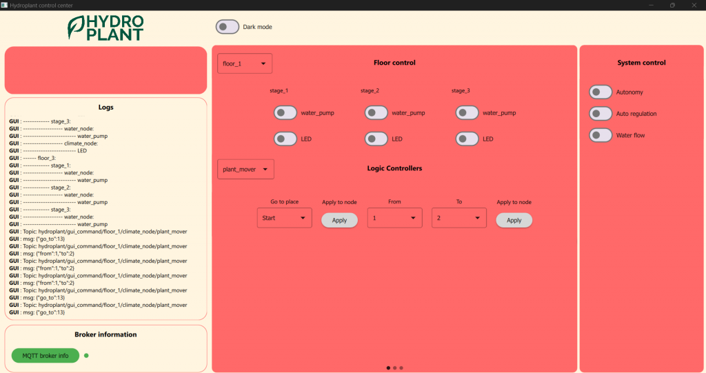
Floor control
The is the main page where the visual elements is dynamically allocated/deallocated based on information the GUI receives about the system from Master Controller. You can control and send commands to the connected controllers and actuators.
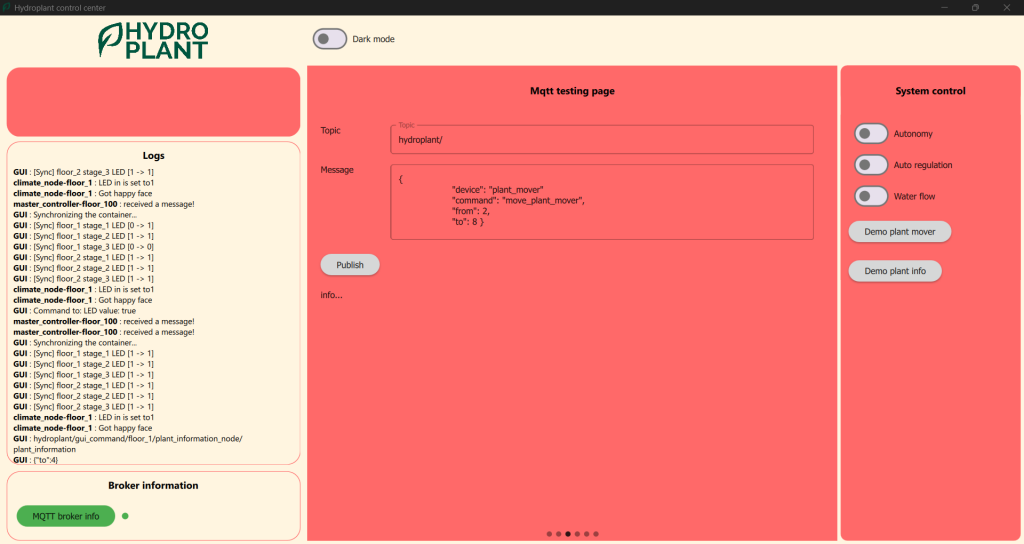
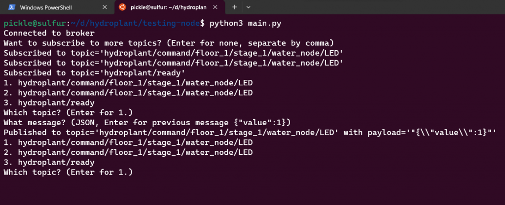
MQTT testing
This page is to send JSON messaged manually to a desired topic. It is mainly used for testing the system manually.
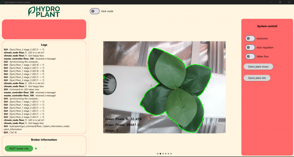
Image show
This page regularly fetches the last image from our image analyzer.
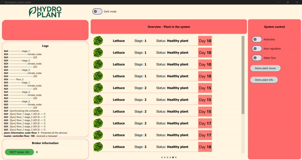
Plant overview
This screenshot illustrates a prototype GUI designed for displaying plant information. The interface showcases fictional data.
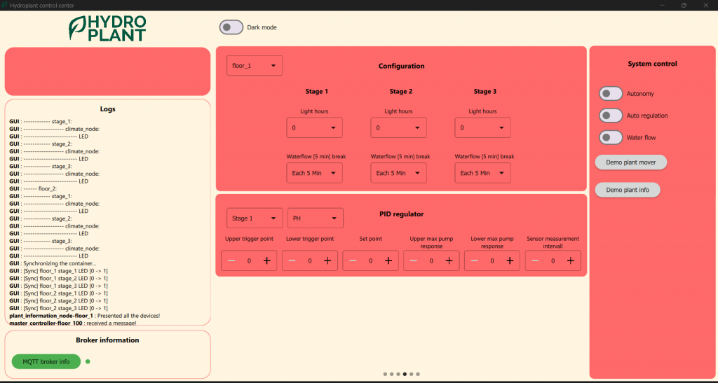
Configuration
This is also a prototype with fictional data for future development. It is designed to advance system configuration for many variables for different floors, stages, and regulators.
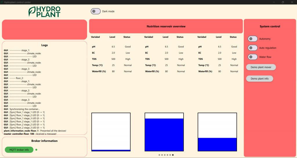
Reservoir overview
This is also a prototype with fictional data. Like the other pages, it follows the MVC (Model-View-Controller) pattern and can display data based on a model or container.
Hydroplant
Snap-on-command
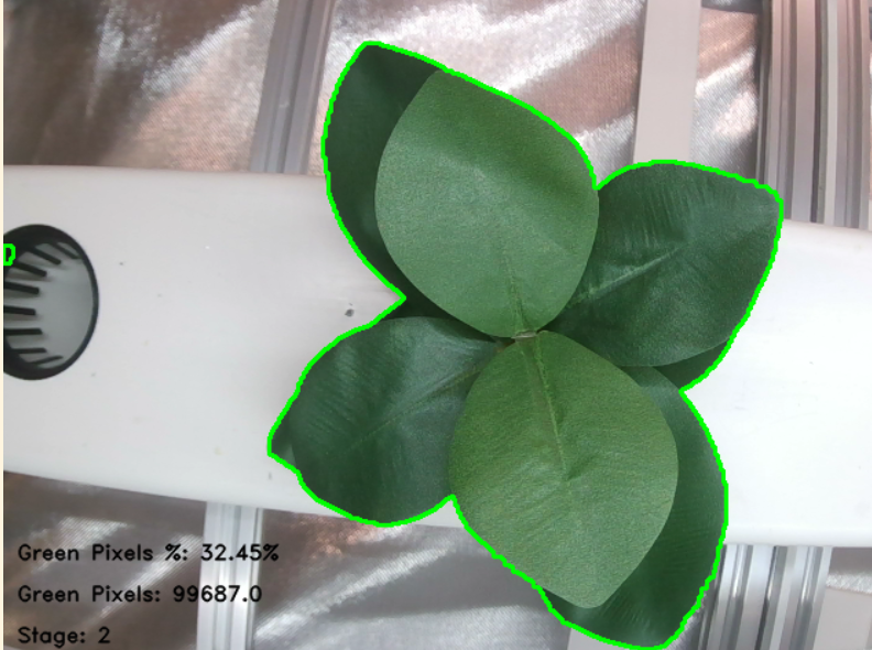
Snap-on-command is a utility designed to interface with a camera device and perform specific actions based on MQTT commands.
It’s capable of capturing pictures, saving them locally, and optionally sending them to another location for further analysis. Moreover, it provides video feed endpoint for streaming and last image taken.
It analyzes the picture with pixel manipulation and decides which stage the plant should be, and sending back the information to the sender.


Oscar Melby
Master-controller
This node is what makes our system a smart system. Master ties every node together, saves data, keeps track of the system, presents usable data to GUI and schedules jobs.
Our GUI never interacts with the system without going through master first, which can verify if the action is valid or not.
Autonomy
Within the master-controller we find autonomy. This is a class which has a job queue where jobs get scheduled either based on time intervals or actions. Every job contains steps which again has deadlines and sleep-times. We do not want to wait forever for a step or job to finish, so it can be killed and deleted. We also want to sleep after some tasks, like when turning off water, as we need to wait for the water to drain out before doing anything else.
Key features
Here are some features which are worth to mention:
- Everything within master is dynamic. If a new node connects, it will subscribe to its topics and create objects to keep track of what is happening with this node. This node will also be sent to GUI. Likewise if a node disconnects; it will delete its objects, unsubscribe from its topics and notify GUI.
- When master sends a command, it expects a receipt. This is to ensure that the task/command was successful, which again helps us keep track of what state the system is in.
- Important data and events gets saved to our MongoDB database, which we can use to optimize our system later on.
- Autonomy communicates through master’s connection, so we can easily keep track of what is happening.
- Every time a state changes, GUI gets notified.
- Master remembers its previous state. So if master for some reason crashes, it can reboot and reset the system to how it was before it crashed.
Testing-node
This node helped us quickly and easily to test sending and receiving of MQTT messages (which often were repetitive). This way we did not need to implement something in master and restart our system the whole time, we could just test one specific thing, and if it worked then implement it. This saved us a lot of time debugging and writing unnecessary code. However, after the new testing page on the GUI, this node somewhat lost its purpose. But can run on Linux, as our GUI is built only for Windows for the moment (this is going to change).
Other work
I’ve for the most part written about master-controller this semester, as this have been my main responsibility, but I’ve also contributed to other aspects of the system. I’ve worked a little on Library, pubsubclient, snap-on-command, other nodes, written, debugged and discussed code mainly Shahin, but also with Theo and Aditi.
What was done this week
This week I’ve made some last changes to master-controller to make for a more interesting demo video. Such as handling receipts from plant-mover and queuing certain jobs when starting up. I’ve also updated and written more documentation which is now available here: https://hydroplant.no/docs/
I also set up static IP addresses for our camera and master-controller PIs on our new router. Noticed this after rebooting camera PI it had changed IP which is annoying when SSH’ing.
Also edited the demo video.
Commits
https://github.com/hydroplantno/master-controller/commit/67673437d09fac542175bcc7d11d58a6cf27a013
https://github.com/hydroplantno/master-controller/commit/70424b30f7371d8c3475eab689ca5de0f72bcf0a
Aditi Deshpande
Summing up everything I have done this semester:
Plant Information Node
- A node/device that calibrates when the system starts
- Listens to commands from the master controller
- Moves to the plantholder place as commanded
- Takes a picture, analyses it and sends prediction to the master controller
I have worked with getting all of this into place. I first worked with plant mover to get the idea of switches, and moved on to plant info node, and perfected it.
This week, I have been touching up and perfecting the Plant Information Node. As you may remember from last week, I wanted to perfect the amount of steps the PIN was taking, as it was off by a little bit. So that was what I was focused upon this week. The plant mover sends the number of steps it takes to get to each switch (aka plant-holder) to the master controller. Instead of relaying that info from master to PIN, I just took it directly from Theo, which is not how it can be in the end, but I figure it is not hard to get that into place. So, this was what I got:
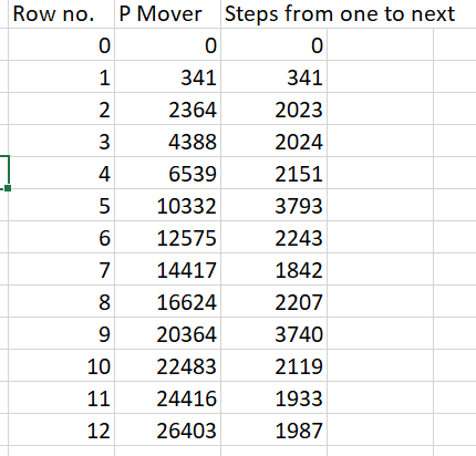
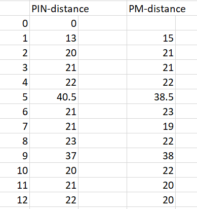
This first column represents the switch/row number, the second represents the number of steps the motor takes in absolute values, i.e. the amount of steps it takes to reach a row from all the way at the start. The last column shows the amount of steps it takes it relative to the previous switch. The last column was what I would be working with. The next thing I needed to figure out was to measure the physical distance between each row in the plant mover and the plant info node. This was what I got:
The only thing left to do was to divide the steps by the distance for plant mover, then I would have the steps needed to move one centimeter, and I could take the average of that:
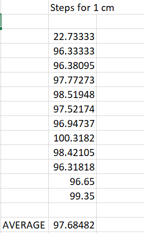
As you can clearly see there was a problem. The ratios were way too different. Therefore, in addition to calculating the steps with the average, I calculated it for individual ratios for *each* place. There is maybe a better way to do this, but in my mind this made sense for now. So, I multiplied the distances from PIN with the average number of steps and the individual ratios. And this was the result:
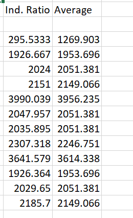
So, I just needed to test this. The steps with the average didn’t work as well, and the individual ratios worked better but still not perfect. So, I tried to calibrate the distance and steps until we had something close to perfect. I ended up going with the individual ratios.
Dev branch commit number 1:
Dev branch commit number 2:
Main branch(after pull request):
Theo Magnor
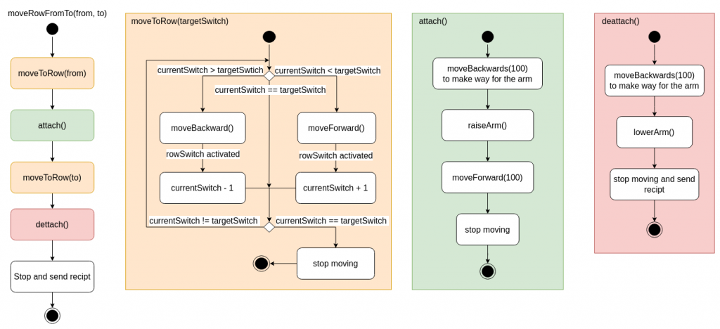
After several weeks of coding, testing, and iteration, my journey in creating the logic for moving plant rows using a servo comes to an insightful conclusion.
Overview
My task in this project has been creating code for the plant mover, which is an essential part of the hydroplant system. The plant movers job is to move rows of plants from a to b, on command form the GUI or autonomy. It moves back and forth under the rows using a servo, and has a switch that is activated when it moves under each row, which is used to keep track of its current row. In the front and end of the plant movers movement range, there are two switches. These are used during calibration to tell the mover that it has reach the front and end.
When the plant mover starts, it goes right into calibration, this is a key part of the plant movers functionality, as the data it gathers is used during its movement. During calibration it counts the number of rows and the steps used to move to each of them, this data is sent to master controller and information node for later use.
After calibration, the mover goes into idle mode, waiting for instructions. When it receives instructions it will be through a command in the MQTT interface, the command will include the action the mover should take, this could be moving a row from 5 to 6. These values are stored and the correct switch case is initiated, running the function moveRowFromTo(from, to). When the function is done, a receipt will be sent back to master.
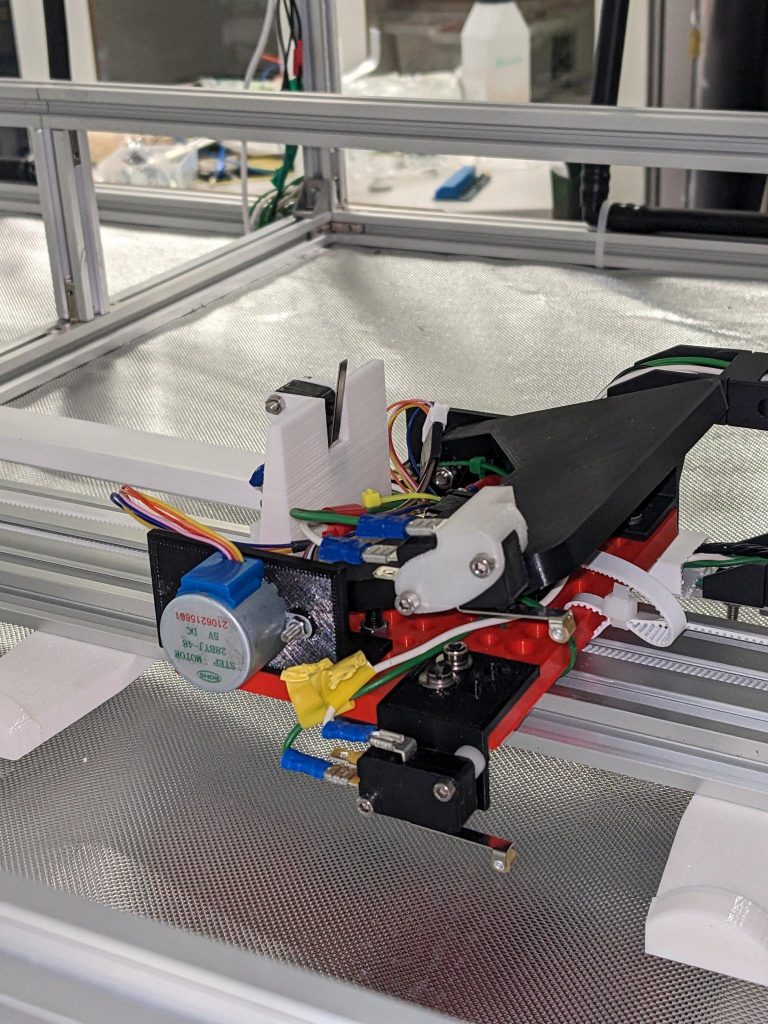
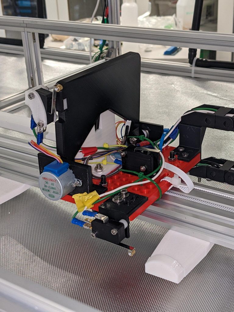
Arm switches and attach switch
The plant mover also has switches for detecting if the arm is raised or lowered, and if it is attached to a row. These would be used to give the master controller a better view of where in the process the mover is. Before calibration, the switches would also be used to check if the arm is lowered. Due to limited pins on the Arduino we needed a interface for reading multiple switch values to the Arduino. Ivan did make a shift register for this, which I tried to implement, but I could not get it to read multiple switches at the same time, which was essential for the logic to work. Due to this and limited time we decided to not use them for now, as the mover still can preform its main functionality without these switches.
What I have learned
Testing
Coding for a physical system has bean quite an adventure, unlike the predictable environment of digital space, the real world adds layers of complexity. This project was no exception, as the biggest hurdle wasn’t writing the code, but testing it with the plant rows, ensuring every movement was precise. In retrospect, testing was a tedious but essential part of the progress, shaping the path from a concept to a functioning system.
Communication
Communication is the foundation of group activities, it allows for coordinating actions, sharing information and achieving common goals. This is something I have been aware of for a long time, but in this project it was really shown to me the importance of communication, and how good communication is essential in complex projects that require integration of various components made by different team members. Effective communication ensures that all parts of the project are compatible and work together seamlessly. Projects can be stressful, but when team members communicate well, and build each other up, working together on the project becomes a joy. And with high morale and a strong team spirit, each setback becomes a learning opportunity, and every success is a shared victory, driving the project forward towards its ultimate goal.
Link to plant mover node on github:
https://github.com/hydroplantno/plant-mover-node
Ivan Bergmann Maronsson
This semester:
My main objective this semester was to design a PCB designed around one of our nodes, the water node. The water node contains different sensors, different pumps with different purposes, electrical water valves, and relays. Throughout the designing procedure for the PCB, I went through 7 revisions until I settled on my final design. Or at least the final design for this semester.
The sensors include an Oxygens Sensor(OS), a Total dissolved Solids Sensor(TDS), an Oxidation-Reduction Potential Sensor(ORP), an Electrical Conductivity Sensor(EC), a PH Sensor(PH), a Non-Contact Liquid Level Sensor(NCHL), a Temperature Sensor(TS), and a Sensor(LSS). Two of these sensors cannot be connected to the same power supply without causing issues, these sensors being the PH and EC sensors. Our solution is to use an Analog Signal Isolator(ASI). This isolator uses an optocoupler to galvanize the voltage it receives so that it won’t interrupt other components. We utilize two of these isolators so that we won’t have any problems down the line when it comes to voltage/signal interference with the sensors. All of the sensors utilize 5V to operate.
The system utilizes different pumps that are controlled separately, to a degree. The first set of pumps that are used are our nutrition pumps that run on 5V. These pumps pump in nutrition when needed, and are determined by the sensors.
We also utilize an air pump that pumps air into all the water containers. and pumps that mix the water in the contains, these pumps operate on 240V.
Then there is the main pump. The main pump either pumps the water up to irrigation or up to the sensors, where the PH, EC, etc are measured. These pumps operate on 12V.
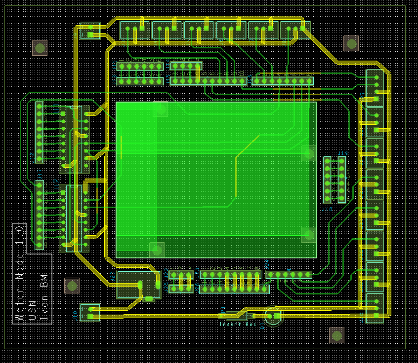
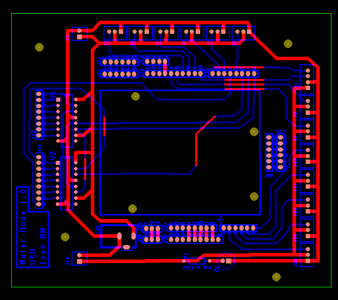
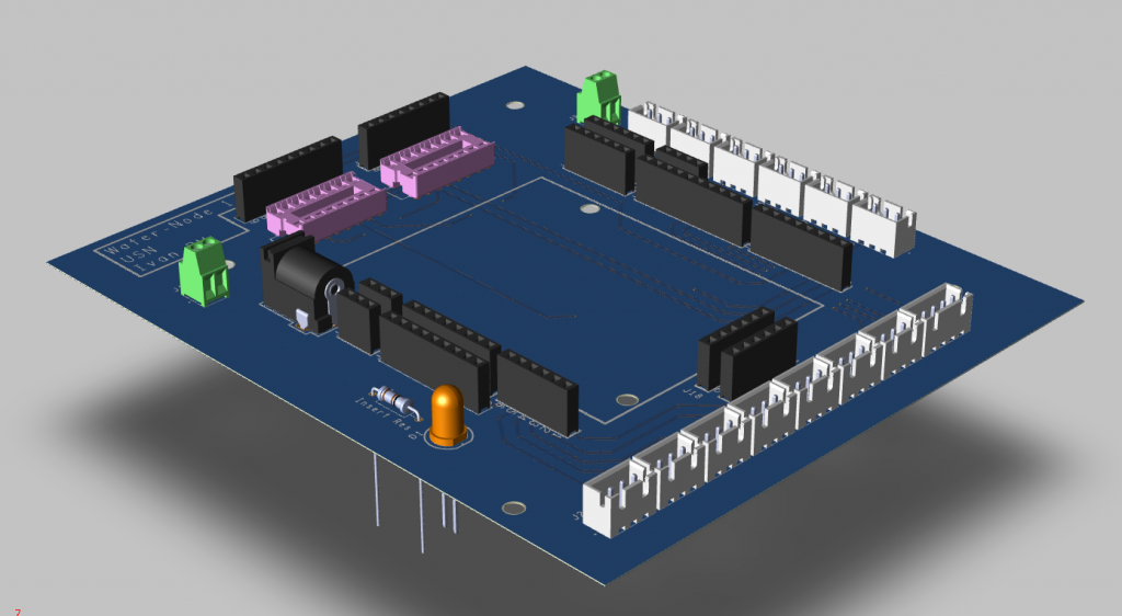
The layout for the PCB ended up looking like this.
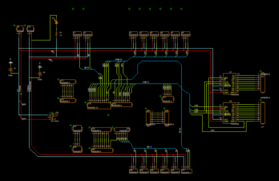
The cluster of headers in the center of the layout are the connection points where an Arduino R4 can be placed. With this Arduino, I am limited to only a certain amount of digital pins and analog pins. From here are most of the analog pins assigned to receive data from sensors, and 4 digital pins are assigned for sensors as well. Then 6 digital (PWM) pins are assigned to nutrition pumps, that pump nutrition into reservoirs when needed.
While designing the PCB I ran into some problems, but in the end, I found solutions to fix my problems. These problems were either that some files would not work ORCAD or that certain simulations did not work for some reason. Or miscommunication between me and the people I ordered the PCB from, that caused some delays in the fabrication and delivery of the PCB.
In the ended up with a PCB design that should work and can be updated for the next generation, where some elements can be changed, and the the dimensions of the board can be scaled more down.
Here are images of my Gerber files as shown before in previous blogs.
Here we utilize ORCADs PCB editor to route all components to all of its connection points, where I follow certain criteria. Where clines that utilize “signals” have a with of 25 mils, and clines that send voltage and ground have a width of 50 mils.
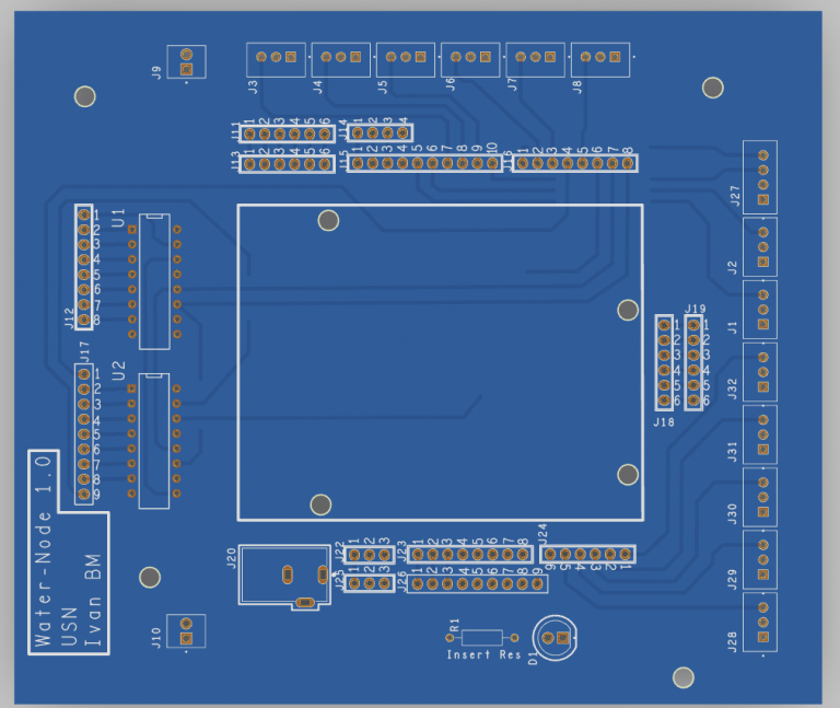
Still using the PCB editor I am able to simulate a 3D model of my PCB, where I am able to see how I mapped my PCB. and where all the components have a marked location.
After this process is done, am I able to generate Gerber files that are used for production. Where I have to make these two layers and others so that a PCB can be ordered.
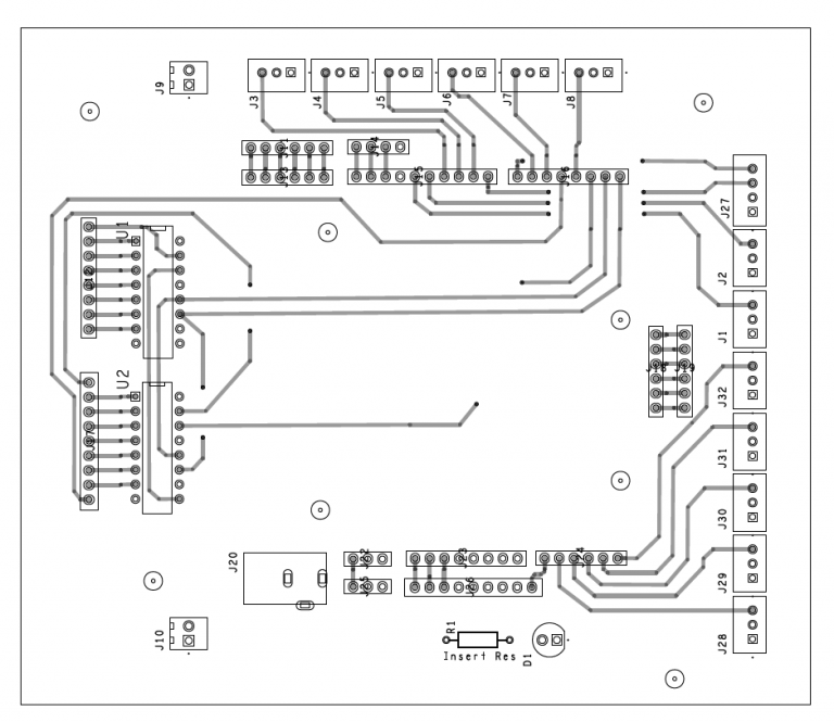
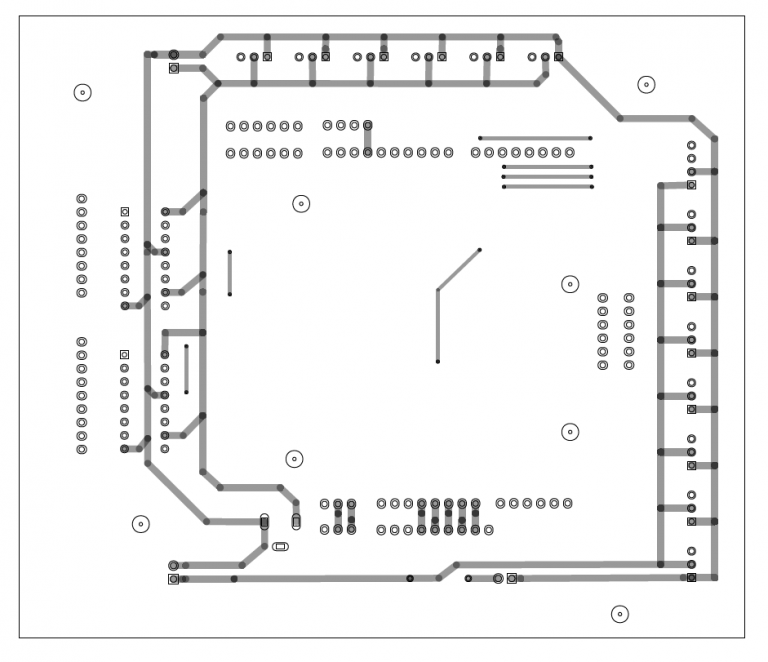
As shown here.
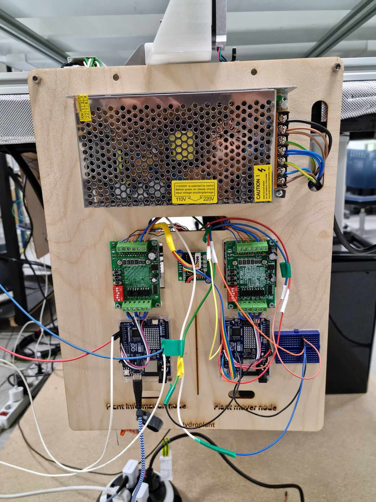
Four nodes were created to house specific units of the system. These nodes are the Plant Information, Plant Mover, Climate, and Water nodes.
The plant mover and plant information nodes are on the same “node” where both units utilize a motor controller and are connected to a power supply that converts 240V AC to 12V DC. These nodes control the movement of the motors that drive both the camera arm and plant mover around the system.
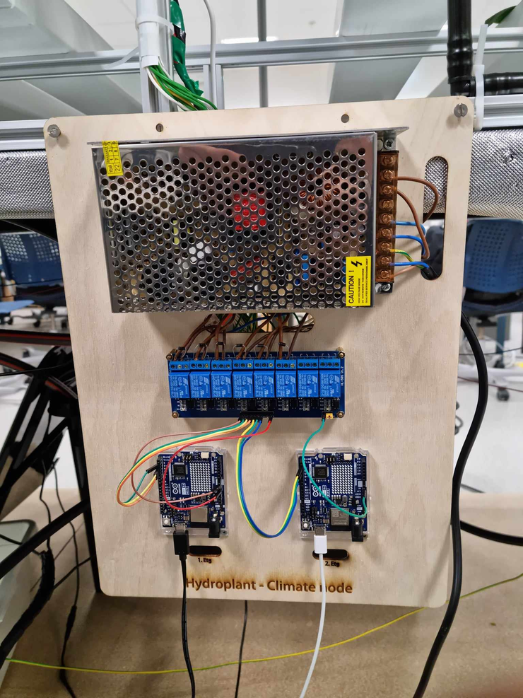
The climate node is responsible for lighting up the system and is connected to a power supply that converts 240V AC to 24V DC. The power supply has enough voltage and amperage to have all the lights on the system active.
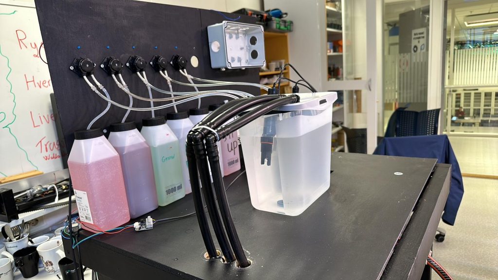
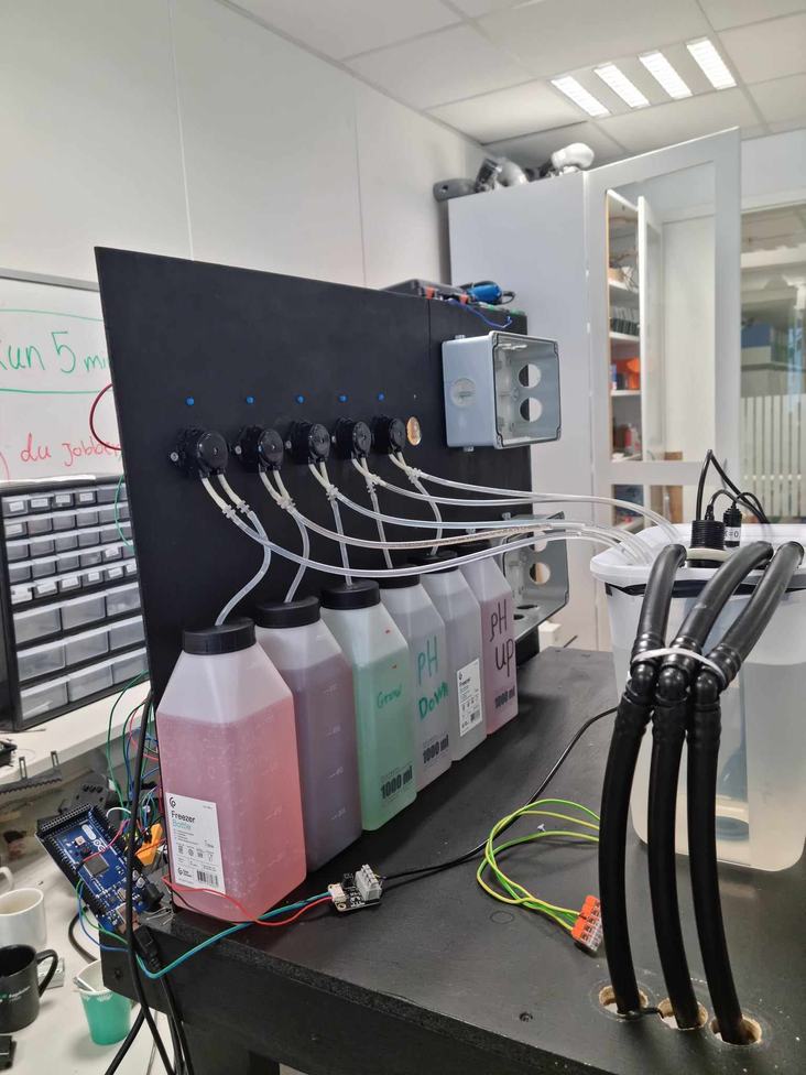
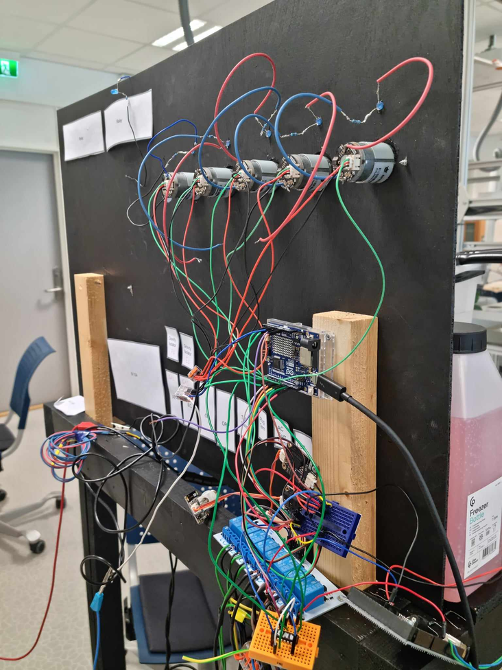
The water node controls the pumps and houses the sensors for the system. And has gone through two iterations. The first one shown below is the first iteration, where it is mounted to the system itself.
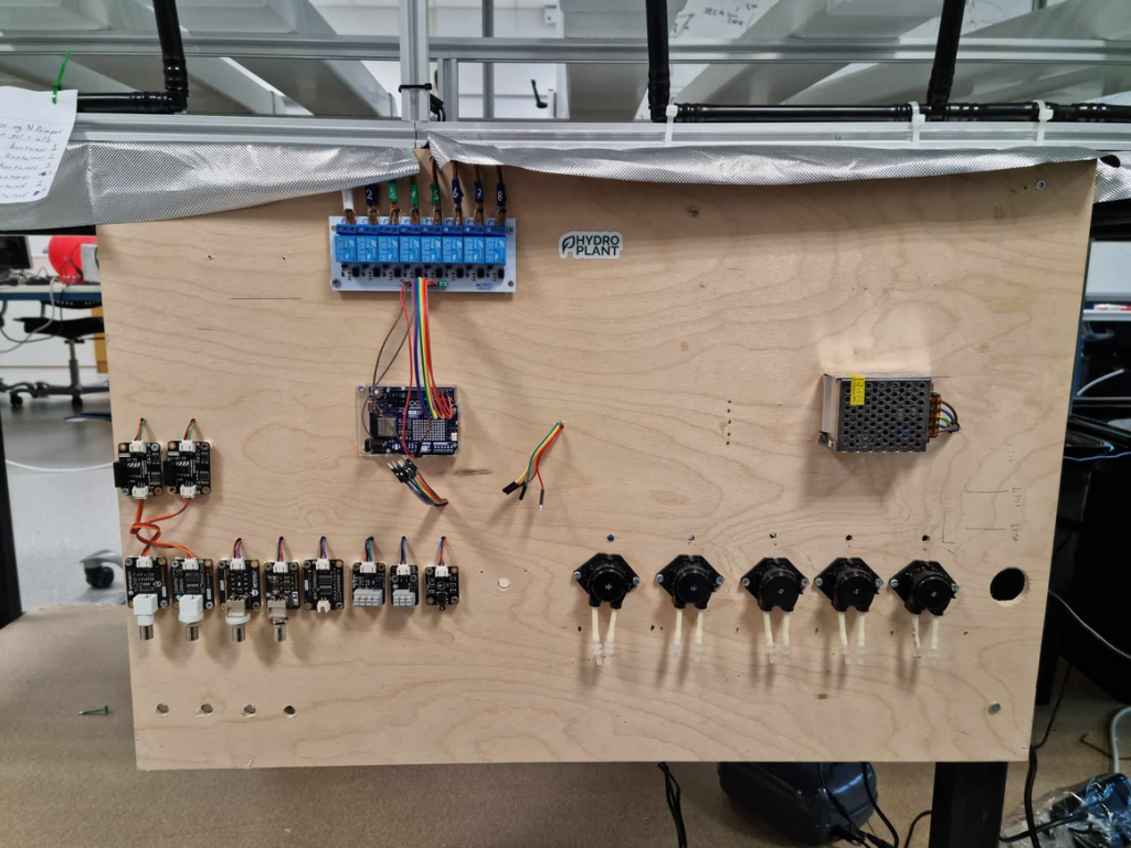
The second iteration is not mounted to the main system but is a standalone system, that contains a water-testing container, where the sensors can detect certain elements of the water, and then proceed with the given data. The water node receives a couple of different voltages to drive certain components. This is 5V for the sensors and some pumps, 12V for other pumps, and 240V for more pumps.
During this semester, I have also been setting cables and setting connections to certain components. From connecting, wiring, and routing for the lights on both floors. Wiring up all 4 nodes so that they receive all the power necessary and are connected to most of their components.
Also when mapping out the pins that are being used, I discovered that we did not have enough pins to control all of our relays for the Water node, but we had enough pins to daisy chain 2 switch registers that are able to control all of the relays, only using 3 pins. But since we are waiting for the PCB to arrive, we are going to use an additional Arduino to compensate for the pins needed to control the water node.
This week:
This week I figured out that the JST connectors that I have added to my PCB are a bit larger than the JST connectors originally on the sensors/pumps. This is an oversight on my part. I should have paid more attention to the dimensions of the components that I already have, and the components I was ordering. This might cause some issues, but can and will be worked around.
The problem can be seen on the board below, where the white components, also known as JST Male Connectors, are slightly wider, than what the sensors and pumps have in our initial system.
I lengthened some cables as well so that tests were able to be done with the mix pumps in each container.
I also tested the SN74HC595n to see if the ICs worked like how I intended. This lead to a small panic, where the datasheet for the IC I was testing, was different than the datasheet for the component we received. After some time, I was able to deduce that, the datasheets were the same, just written differently. And connecting the ICs, gave the same results as when I simulated the IC.
I added my entire PCB design from ORCAD to GitHub.
Now we are currently waiting for the PCB after some delays, and should be coming this Monday.
Here are my PCB files for this project:
https://github.com/hydroplantno/Water-Node_1.0/commit/dc89af421357a03ab102549f051126413ff3136f