Shahin Ostadahmadi
This week, I have been testing different parts of the system with the group, fixing issues, implementing new changes, and repeatedly testing the system. I also implemented some additional code for nutrition regulation. Furthermore, I have set up the nutrition station and connected pipes according to the design I made last week (I will post pictures next week). However, we were not able to test the regulation code because all the pins on the Arduino have been utilized. Ivan has started to implement a solution using shift registers to extend the number of available pins on the Arduino. We will review the design of the shift registers next week, and I will start writing code for interfacing with the shift registers before we can proceed with testing. However, we may be able to test just the nutrition regulation if we unplug some of the actuators. I have also been testing some code with Theo on the Plant-Mover node. We still have the network issue that we need to figure out. We plan to set up a new network on Monday using a router instead of a Raspberry Pi, as it is currently set up.
Commits
Commits are only visible to members of the organization.
https://github.com/hydroplantno/water-node/commit/e6f6570baa4b98ae76c0c488449d2e4e9c8d8e0fConnect your Github account
https://github.com/hydroplantno/gui-node/commit/6c0a5957978c96e11992d17daaa906fbda93570aConnect your Github account
https://github.com/hydroplantno/library/commit/ef20bd4157b2ead9e07f9a6b7ed4c89886d1643cConnect your Github account
https://github.com/hydroplantno/library/commit/ef20bd4157b2ead9e07f9a6b7ed4c89886d1643cConnect your Github account
https://github.com/hydroplantno/climate-node/commit/24342ea50b9b2c71e57939652ba1352a4ae8a158Connect your Github account
Oscar Melby
Master-controller restructure
As mentioned in the previous blog, I found out that the structure for keeping track of everything happening, connected nodes and etc. was not best. This week I’ve rewritten everything to use the “new-dynamic-structure”, not that the previous one were not dynamic, but you get the point.

Might not look like much, but its honest work ![]() , and its in Python so each line is more “dense” than in e.g. C++ (no braces for example). Still have to implement the interface for autonomy which runs within the master-controller, but this should be easy due to how the new structure is set up.
, and its in Python so each line is more “dense” than in e.g. C++ (no braces for example). Still have to implement the interface for autonomy which runs within the master-controller, but this should be easy due to how the new structure is set up.
We have also tested the new code and found bugs which there were no shortage of. Most of these were really simple fixes, but still takes time to test and find them.
Why even rewrite if the previous iteration was working anyways?
The old iteration was smacked together to “just work” and did its job in the start. But when complexity was added such as scheduling jobs through autonomy it got quite clunky to work with. When a node connects it has a lot of things it want to share with master-controller and couple of things it want to know of (commands and such). If we were going to have lights on between 7AM and 9PM we would have to do something like this:
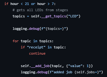
Since topics include all topics the system knows of we need to find the ones only containing LED. Then for every “action” if you can call it that, there exists a receipt, which is the response from the node doing the action. This is to know if what we sent actually happened or not. Perhaps not the best way to do things?
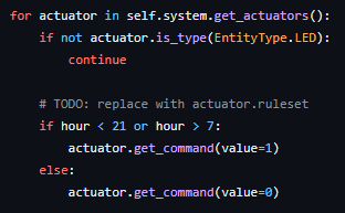
This is the new way. Much cleaner, could probably be done even better, but works good enough. Its easier to see whats happening at least. Have no clue about performance differences, but in our case this is irrelevant. As we have all the time in the world to react and handle things.
Example is not 1:1 as the last example still needs to schedule jobs, but imagine this as just taking the returned value in get_command and putting it into add_job. The first example does not show turning off the lights either.
Commits
Commits are only visible to members of the organization.
https://github.com/hydroplantno/master-controller/commit/0d56b3458a221ceb290e26e5518542dc9ea98ba4
https://github.com/hydroplantno/master-controller/commit/fe66d53cacb775440b8f122be52698d5f9d51f45
https://github.com/hydroplantno/master-controller/commit/3684306860c13185296e3745fe85779c438a8d47
https://github.com/hydroplantno/master-controller/commit/ed57d3a2a7e27808899f3ef5bc8fba62915ead1c
Aditi Deshpande
This week I fully focused on image analysis, but on Wednesday I decided to push my dev branch into main branch so that in main there is the “right” code, and copy main into another branch in GitHub. As Git obviously does not want to make everything easy for you right away, I ran into merge problems. Thankfully, Shahin was there as well and we fixed it together. So anything new I will implement in dev.
So, Shahin and I talked, and he talked about a new type of convolutional neural network that segments images, and is used in medicine. As CNNs are something we are familiar with, he suggested that I take a look at it. And I started researching it, and the basic gist of it looks like this:
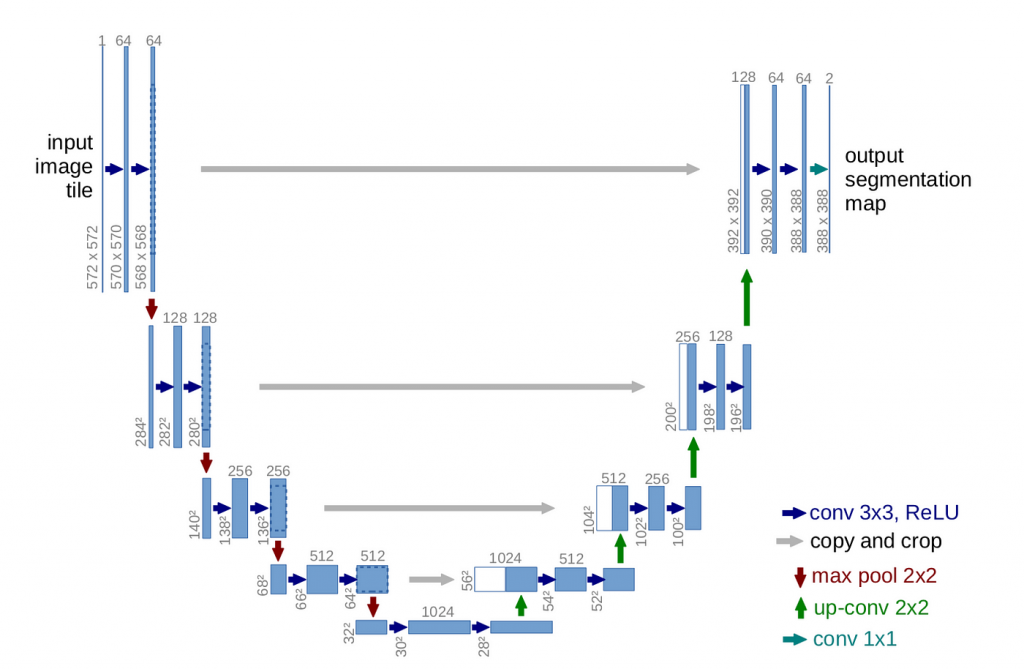
The U-Net is an encoder-decoder convolutional neural network. It uses fewer images to predict a result. The encoder part figures out “what” the image is. It contains two convolutional layers, then max pool(taking the max value of 4 frames), ReLu(taking only positive values and setting 0 for negative values), and padding(adding a layer around the frame). The grey arrows are the skip connections, which is the highlight of Unet – They use the information from the previous steps to understand the “where” of the image- in the second part, the decoder. This helps in segmenting the images and placing the images where they are supposed to be.
So, the steps for implementing U-Net are:
- We need a dataset. We have found 1600 images of a plant(unsure which species) from a seedling to a fully grown plant. However, in the first iteration, I only used 400 pictures.
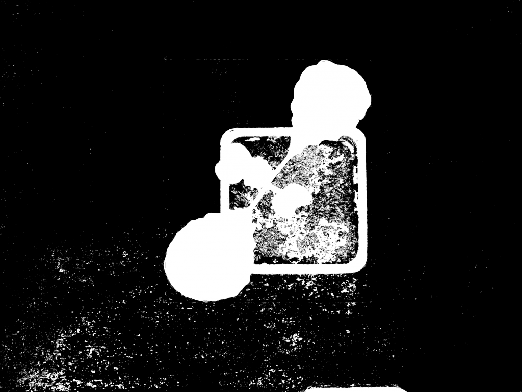
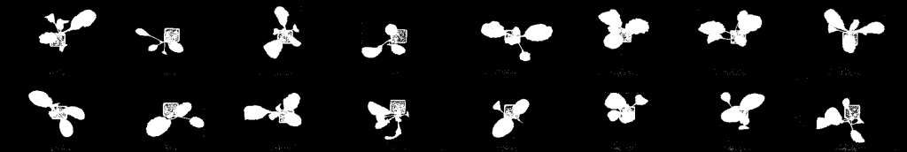
- We need to mask the images. So, the points of interest are in white, and the rest is black. So for example if the original picture looks like this:

Then the masked image looks like this:

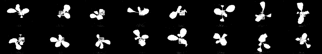
To get the code to highlight the important you need to specify the HSV color range it needs to look at. That adjustment took some time. I will upload all the code to GitHub by next week. So in the end I got 400 masked images of the plants. The problem was the pictures looked like this:
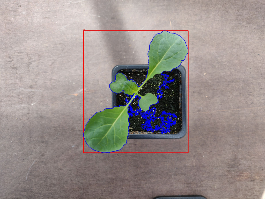
I tried various types of code to crop the pictures until the red border, as the pictures were way too large with 6000×3000 size. This would take way too long to train and everything outside the red border was useless. That didn’t work, and I had no choice but to use pictures as it was. But I will look into it in the future. The masked image looked like this, it unfortunately took the flower pot as well(I suspect this was because the color resembles green) but I figured it wouldn’t do any damage for now.
- Programming the Encoders, Decoders, the Convolutional layers with Pytorch in Python. I used this tutorial for doing it: PyTorch Image Segmentation Tutorial with U-NET: everything from scratch baby He explained everything from scratch which was very useful.
- Transforming and normalizing the pictures, so that they are ready to be used by the training part of the neural network.
- Train the model, in a batch size of 16 images, and in three epochs(so train and test 3 times with the same pictures), error correction, and backward propagation and checking the accuracy.
So I trained the model, and these were the predictions. The code gives you a series of predictions, highlighting the points of interest:
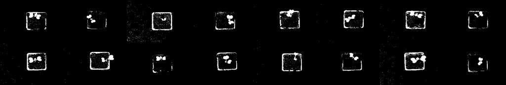
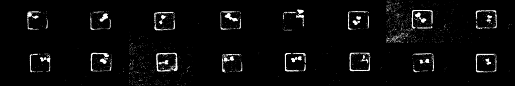
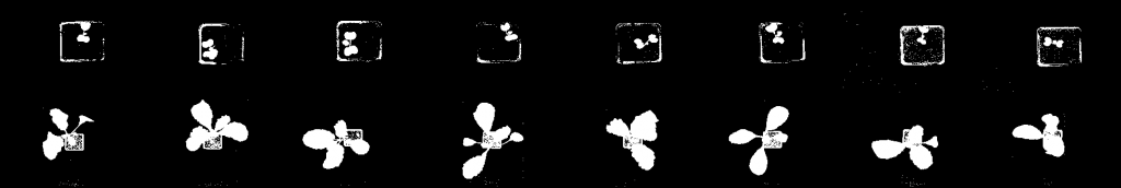
and a couple more pictures like this. So it arranged the pictures in increasing size. So, the truth is: that I don’t exactly know what it means that the neural network thinks this is interesting. I think it comes from the fact I didn’t even know what I was looking for when I tested the code, which resulted in me being a bit confused. So I’ve decided to first define what I am looking for: I need the code to divide the pictures into three sections, one where the plant is a small size, then a middle size, and then big and ready to be cut. So I need three output vectors. It should be fully trained, and based on the training it should classify a new picture into one of the three sections and send the decision to the master controller. How am I going to get this neural network to do my bidding for me? Well that’s for future me to find out ![]()
Next week:
- Figure out what I want from image analysis.
- Make point 1 happen.
- Talk to Shahin and how we are going to figure out the communication from the machine learning algorithm to the master controller.
Code:
- Commits made into dev now( which are in main now):
https://github.com/hydroplantno/plant-information-node/commit/32dc90ee7a68728a8d64f24cebc728c493beb4e4Connect your Github account
- Main branch looks like this now: https://github.com/hydroplantno/plant-information-node/tree/mainConnect your Github account
- Pm_move – old main is pushed into this branch: https://github.com/hydroplantno/plant-information-node/tree/pm_moveConnect your Github account
Theo Magnor
This week I have done both physical and digital work on the project. I have drilled, glued, and screwed to fit some plastic parts that will be the contact point to the rowSwitch at each row. Before this we had a temporary solution that used a clunky wood beam, it worked but was not elegant in any way. After testing the plastic pieces I can confirm it both looks and works better, as there is no moment and higher precision compared to the wood beam.
In the code we have made some changes to how the moveRowFromTo function works, it now uses two states to handle the logic of calculating both move directions. I still need to test this functionality, and will most likely make some changes.
Commit
https://github.com/hydroplantno/plant-mover-node/commit/7f3a196c0fb28395e85b91c7ae256cae68ec59d8Connect your Github account
Ivan Bergmann Maronsson
This week I discovered a problem that I should have noticed earlier. That problem was that I didn’t think that the relays needed digital pins from the Arduino. This happened after I found out that we only have 14 usable digital pins on the board, which left us with only 4 digital pins to connect with our corresponding relays. The solution we came up with was to use SIPO switch registers. Where we are able to use 3 of the digital pins to daisy chain two switch registers together. So that we are able to send out information to 16 relays using only three pins. Then the last digital pin will be used to control sensor-relay. And I also forgot about one of the sensor needing 4 pins rather then three, which has been changed and fixed in my design below.
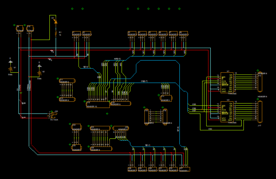
Schematic of Revision 8
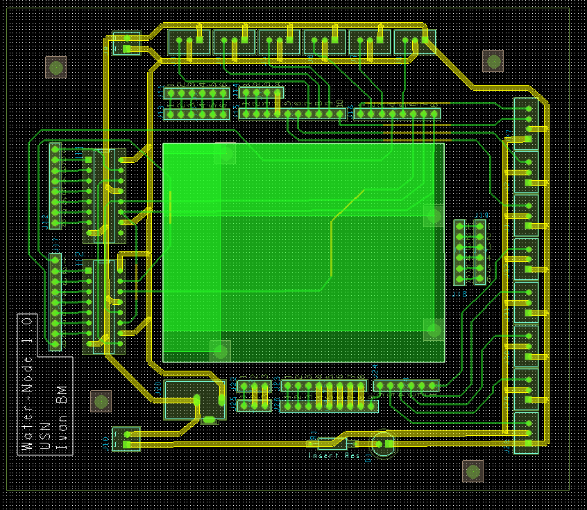
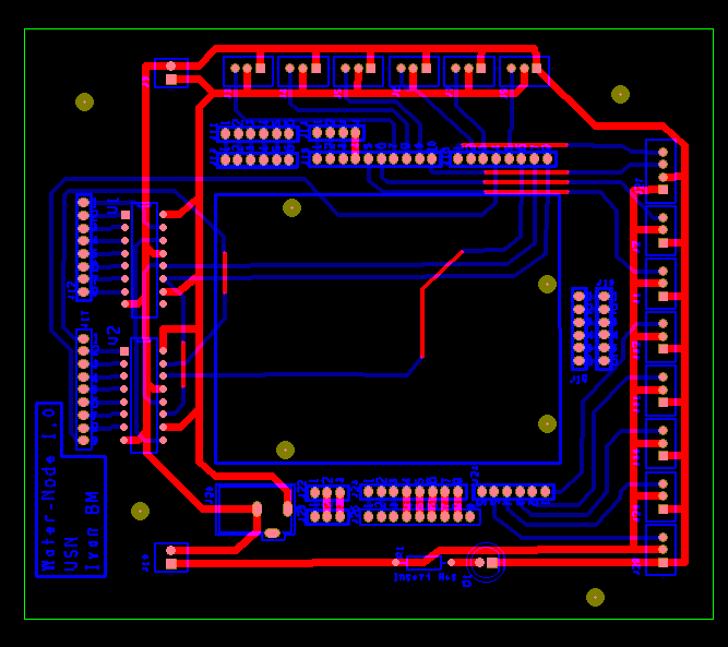
Layout of Revision 8
And here is a 3D model of the PCB with and without its components on the board.
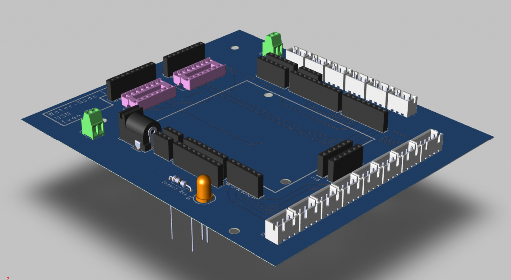
3D model of the PCB
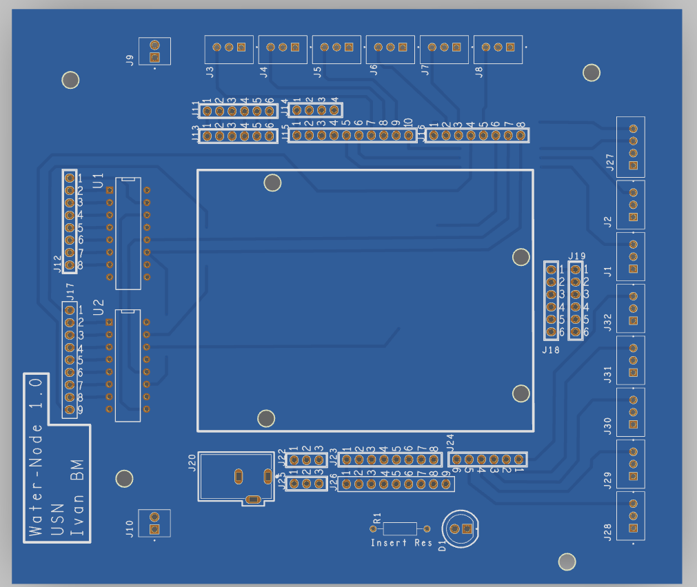
Top side view of the board without the 3D models
And here are the clines and silk-mask for both top and bottom layers.
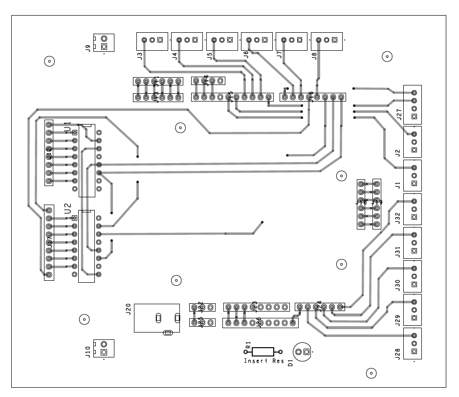
Top layer
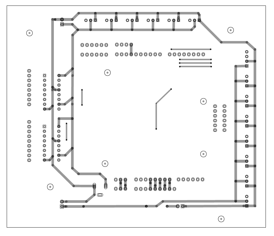
Bottom layer
After simulating the board and checking if I had and DRC problems (There were none), I was ready to make my Gerber files. This is done by changing the certain colors and layers to shop up on certain times, and saved appropriately, and then later put together into another software to simulate the Gerber file itself.
Gerber file simulation