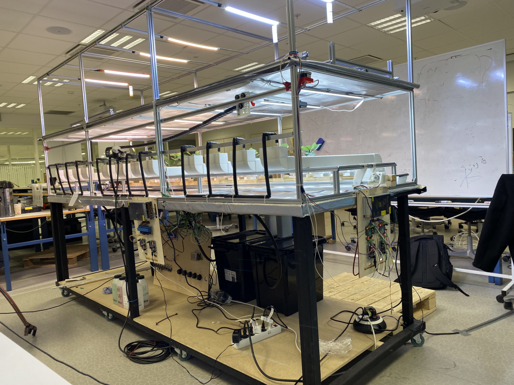
Welcome back to this weeks blog! We had a demo for a local journalist on friday, and the picture bellow describes our sitiuation perfect. It was good to find out more issues with our system, this time was the network which we never have had problems with. The way we did the streaming may be a cause due to more network traffic than our raspberry pi which acts as our router can handle. We will debug more the issues next week. The demo also thought us the lesson about our most critical points of the system, since all our communication is based on our local network, the network needs carfully configuration to minimize the risk of failing.
However, we had a great demonstration of the system and we got some training to for the exam.
Shahin Ostadahmadi
Microcontroller
Nutrition regulation Physical
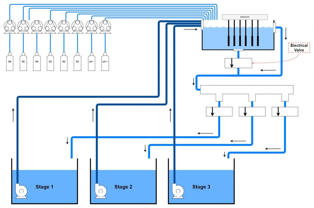
Last week I made a physical design for nutrition regulation as you can see in the diagram below.
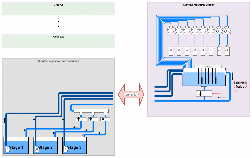
This week we received most of the equipments and started to implement the solution. We are still waiting for three of the electrical valves to start testing, they will arrive next week. However, we decided to adjust the design to fit with the physical structure of the system. The changes will be as the diagram shows below. I’ve started with the construction of the Nutrition-regulation-station and I will be finished with that next week. We will then connect all the electronics to it and test it as a whole.
Nutrition regulation code
I have implemented the code for the nutrition regulation controller, and I will test the code when the physical construction is done. There are many variables to consider in the code, and some of the most important are:
- The code has to be state machine-based so the microcontroller can do other things too
- All the actuators and sensors have to change their IDs with respect to the current Reservoir it regulates since we are storing the data in the database, we have to know which stage the values belong to
- The regulators such as pH and EC have to change the config values such as set_point(ex: EC should be 2.2 in stage 2, 1.8 in stage one etc.), upper -and lower reaction values
- Every time we regulate a reservoir, we have to give the system enough time to be sure that the nutrition is mixed well enough with the water before moving to the next regulator or stage, also known as “Stabilization mode”
- After each stage is done, we have to give the system enough time to “flush” the nutrition box before moving to the next stage
- Before each stage, the controller has to route the input and output water from/to the correct reservoir.
The state machine diagram bellow shows the states the controller can be in. There is also different states the system can be in when the system is in “Regulate pH“ or “Regulate EC“, but i have excluded those state for the simplicity.
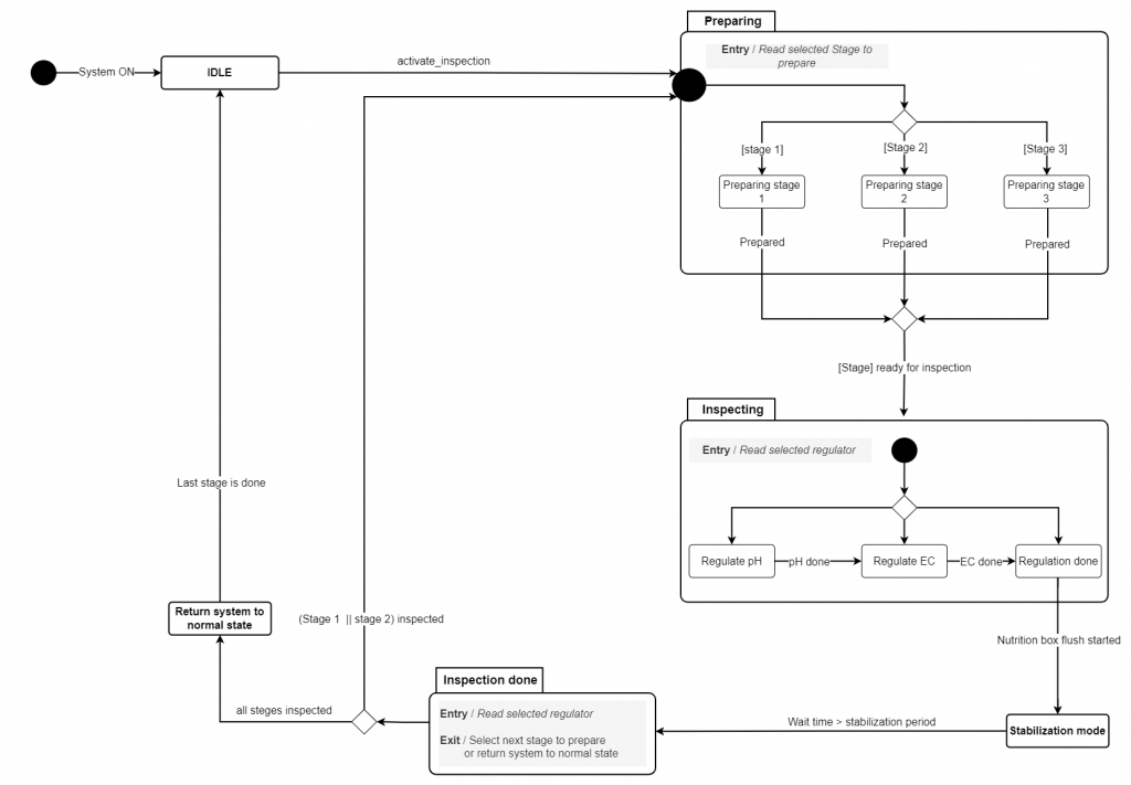
I’m excited to test the controller next week!
Communication
We had some problems with the communication for all our nods, they lost often the connection to the network and Mqtt-broker. I implemented the solution for the issues in the library code. The nodes now check if they lost connection to either the broker or network regularly and when they are trying to communicate with outside itself, they are automatically connecting and running all necessary activities for reconnection. The solution was tested for a period of 2 hours, and the node still was connected to the system. The test is approved.
GUI
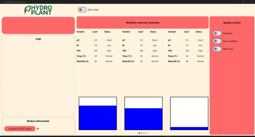
Testing out some visualization for reservoir overview. The goal here is to show information for all the reservoirs. As you can see in the picture below, the page shows the data for our three reservoirs with visualization for water level. The data for now is random and it is meant to be for testing. However, since the GUI is based on the framework Model-view-controller, the visual items can be controlled by changing the interface for data-input. The data will be replaced with real data and tested when we have implemented the interface.
I also added some extra buttons to send commands to our camera in the system to stream.
Commits
Commits are only visible to members of the organization.
https://github.com/hydroplantno/library/commit/cdf08ba6ed095d532358f7a99589e4fe5bb11342Connect your Github account
https://github.com/hydroplantno/gui-node/commit/afb3f33fae9728a18e60ba5ca379110718c9c105Connect your Github account
https://github.com/hydroplantno/gui-node/commit/ce693c84900667ef5e35c80443bf171472005958Connect your Github account
https://github.com/hydroplantno/water-node/commit/684cde97c46eb44ee3f2a3abaab66ada6e2cff67Connect your Github account
Oscar Melby
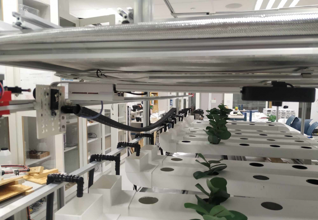
Tested the whole system again this week as we had an interview with a local journalist, and wanted to show a demo. Almost everything which could go wrong went wrong, but I think we learned a couple of things from it. Here’s a picture of the system with running water and all lights on.
Restructuring master-controller a bit
While explaining how I imagined how autonomy should be implemented further, Shahin came up the idea of restructuring how I had done things so far. After a bit of thinking and discussing, this seemed like a better way to do things, than I had done so far. Issue is; the structure right now is a bit complex while being simple at the same time which makes things a bit tricky. It’s hard to follow whats happening as everything is almost in a “flat” structure, which really doesn’t represent how the system is set up. It was great for getting things setup and tested fast, but might not be the best structure when adding more complexity and logic to the system.
As of how things were set up it looked like this:
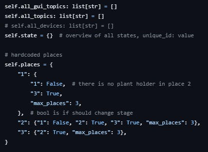
If you for example wanted to turn on all lights in the first floor, you would need to find every topic containing “LED” and “floor_1” in all_topics. You would also need to filter out the “receipt” topics. Easy to do, but maybe not the best way to handle things when there is a lot of components, actions and receipts which is going to be dealt with.
Shahin drew a sketch of how we could implement the new structure into master-controller. Somewhat like how the GUI is implemented, however this might be “easier” for GUI to do as all the topics are already made for it beforehand by master.
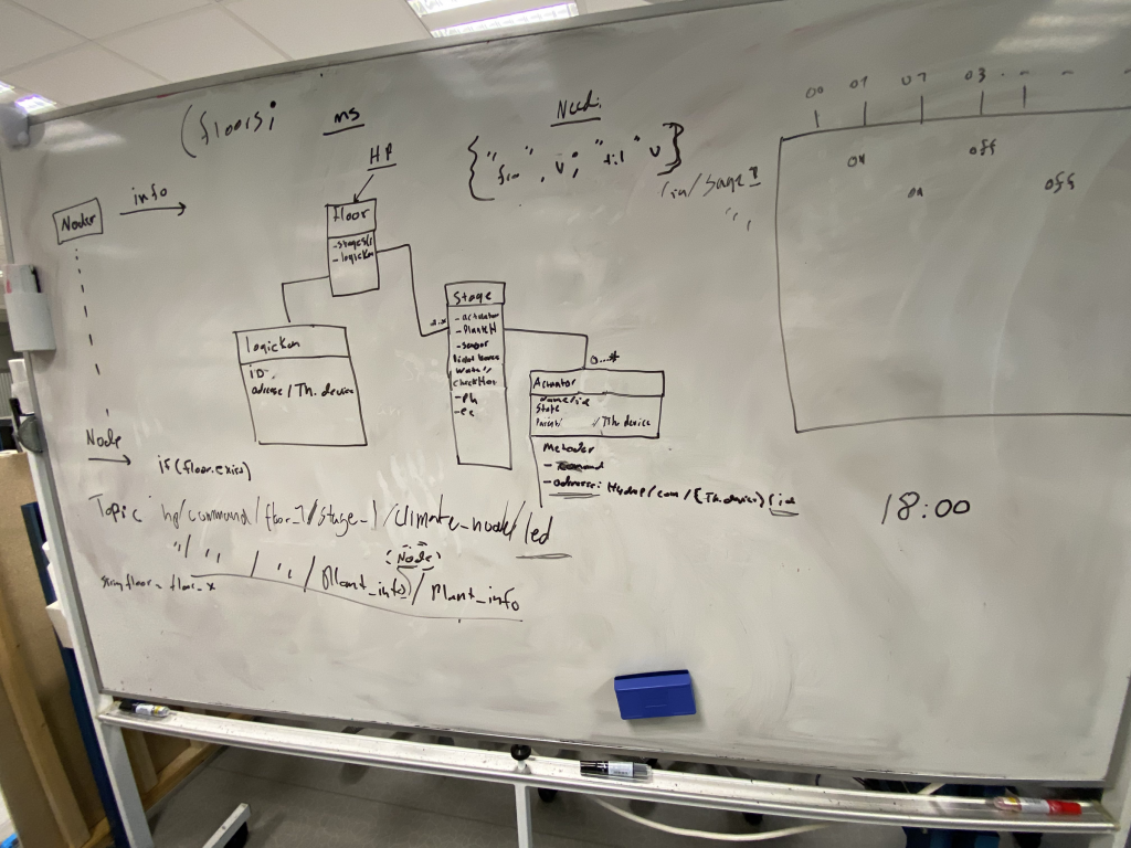
The sketch might not make so much sense, but helped me a lot to rethink how it could be done easily and dynamically.
Have started to add some things, but are not done yet. The “old” version of master-controller still works, and will be used by the others while I’ll change to the new structure and test things, so I won’t halt any progress for the others (hopefully)
Snap-on-command
When we stream a video feed from the camera to our Flask app, we would constantly be “loading” in the browser. The refresh icon would load forever without finishing as we got frame after frame on stream. The stream was smooth and worked as intended, but would for some reason crash and not catch up again. We thought this could be because we looked at the “embedded video stream” directly and not including the stream as an embed on another page. So added this, and things seems to be working fine so far. While running the stream however, our network tends to freeze and be slow. If this is a coincidence or because of the video stream we don’t know yet. Looking at the network overview the traffic doesn’t look absurd and has not been an issue before.
Commits
https://github.com/hydroplantno/snap-on-command/commit/369f80cf427a3eae8e788334575a975283a4b51cConnect your Github account
https://github.com/hydroplantno/master-controller/commit/93ed56036aeeaa87053f6a9e92569b567b609124Connect your Github account
https://github.com/hydroplantno/master-controller/commit/98433725b0f5758a4fbb14612d88aae8b24f867aConnect your Github account
Aditi Deshpande
This week I’ve mostly focused on other subjects, but on Monday, I worked with Shahin to fix the camera on the Plant Info Node. We got the Raspberry Pi, connected it to a USB camera, and attached it. Oscar and Shahin had previously figured out to how to get a live stream from the camera, and we managed to configure everything. I worked on how to combine both the movement of the PIN to the right place and also send a command to take a picture to the pi and make sure it is saved in a place. I’ll be further working on the image analysis of the picture using a simple way of just counting green pixels and determining if the plant is ready to move or not. On Friday, I worked more on testing and fixing small problems around the total system. We got the PIN to move to the correct place, take a picture from the camera, and save it.
Here’s a picture of how we attached the camera:
Here are the code commits:
- Moving to the right place with switches : https://github.com/hydroplantno/plant-information-node/commit/f1988705669cd3558389a866a5c5607fa63cf36fConnect your Github account
- Taking a picture: https://github.com/hydroplantno/plant-information-node/commit/44009c37489c59a6ea4e715f5f64942e95c22c26Connect your Github account
Theo Magnor
This week i got the main functionality of the moveToRow function working, what remains is finalising and testing the sending of receipt. We want the master controller to revive the plant movers location after each operation. Next week the physical build of the small arm that will push the rows should be done, this means i can start testing and debugging the code i have written for lower/raise arm and attach/detach.
Here is the the moveToRow function
void PlantMoverController::moveToRow(int targetSwitch){
    while(true){
        // Communication
        if (communication_interval + 1000 > millis()){  // Check if it's time to ping
            communication_interval = millis();  // Update the last communication time
            m_communication->loop();  // Perform the communication loop
        }

        // Moving Backward
        if (backward == true){  // Check if the system should move backward
            my_stepper->moveBackward(stepsToMove);  // Move the stepper motor backward
            if (m_row_switch == true) {  // Check if a row switch is activated
                if (targetRow == m_currentRow){  // Check if the target row is reached
                    my_stepper->moveBackward(20);  // Move a bit more to deactivate the switch
                    backward = false;  // Reset move backward flag
                    m_row_switch = false;  // Reset row switch flag
                    state = s_idle;  // Set state to idle
                }
                m_currentSwitch -= 1;  // Decrement the current switch count
                m_row_switch = false;  // Reset row switch flag
            }}

        // Moving Forward
        if (forward == true) {  // Check if the system should move forward
            my_stepper->moveForward(stepsToMove);  // Move the stepper motor forward
            if (m_row_switch == true) {  // Check if a row switch is activated
                Serial.print("Moving forwards, currentSwitch: ");
                Serial.println(m_currentSwitch);
                if (targetRow == m_currentSwitch){  // Check if the target row is reached
                    my_stepper->moveBackward(20);  // Move a bit more to deactivate the switch
                    forward = false;  // Reset move backward flag
                    m_row_switch = false;  // Reset row switch flag
                    state = s_idle;  // Set state to idle
                }
                m_currentSwitch += 1;  // Increment the current switch count
                m_row_switch = false;  // Reset row switch flag
            }}}}
In the code we can see that move direction is dependent on two bools;”backward” and “forward”. Here is the code for calculating the move direction:
     case PlantMoverController::States::s_calculate_move_direction:
    {
        if( m_currentRow > m_targetRow){
            Serial.println("backward");
            backward = true;
            state = s_moving;
        }

		if( m_currentRow < m_targetRow ){
            Serial.println("forward");
            forward = true;
            state = s_moving;
        }}
When the state is switched to moving, the moveToRow function is run.
Next week i will test the code i have written for raising the arm, i will also have to figure out the amount of steps it takes to move the arm between its intended states.
Ivan Bergmann Maronsen
This week I found out, that my initial design would not be able to do what I wanted it to do. So instead we are opting for a design that only has 1 LED to “show” when the sensors are on. Now that I have fixed this “issue” I am able to order my PCB this coming week.
Also this week, I and the others set up the lights for the second floor, and we connected everything down back to the “Climate node”. So that all the lights are now controllable through the GUI so that they can be turned on and off individually now.