Introduction to This Week’s Update on Smart Systems
We have implemented several functionalities to the system this week, and tested them. The next week will be fixing and debugging the issues and approve functionalities to be merged into master for the first release after passing the test!
Software development is like hammering a nail. Either you hit it right on the head or you smash your thumb.
Unknown
Shahin Ostadahmadi
GUI
Algorithm
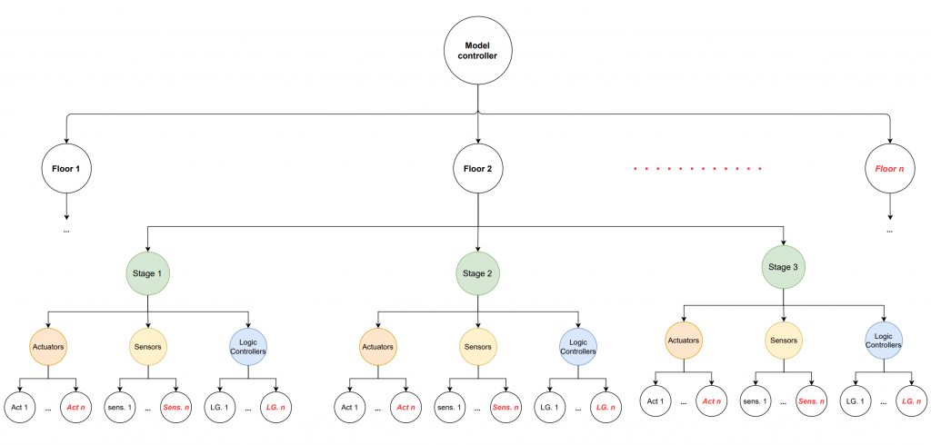
Last week, I implemented a custom container that mirrors the physical system in order to allocate visual elements such as switches, buttons, and so on. The information about the system is sourced from the Master Controller and consist of a comprehensive list of topics. These topics correspond to various sections, such as commands, calibration values, logs and they belong different floors, in each floor the can belong to 3 different stages, and finally each of them belong to a node in the floor. I implemented an algorithm to scan this list, sort it into a structured format, and dynamically create different objects. These objects are then placed in the custom container, which the GUI utilizes to generate the visual elements.
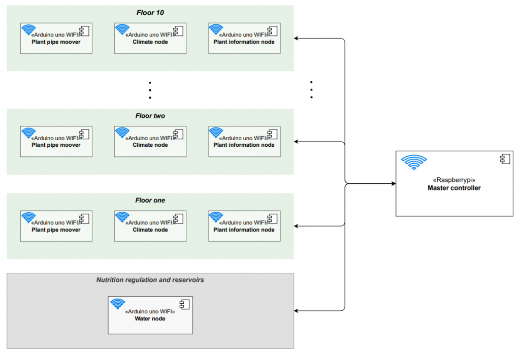
To get the Whole picture we can look at the whole system with several floors, and then you can look at the illustration for one floor in the next diagram.
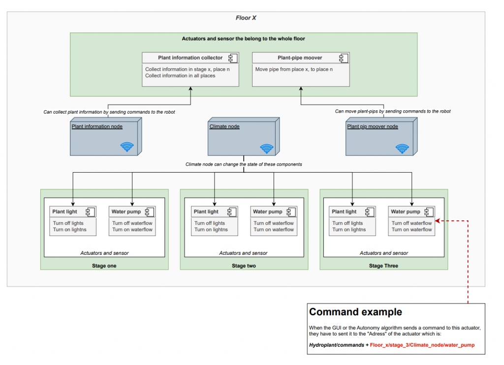
Visualization that show how a single floor is deployed with an example of a command.
Here you see the activities when the different nodes presenting them self to the Control Master. The diagram illustrates the activities and the message format it will be sent. The algorithm receives the information (see “information example” for format) and sorting them and store them in the Custom Container. Se the diagram “Custom container” to se how the data is stored.
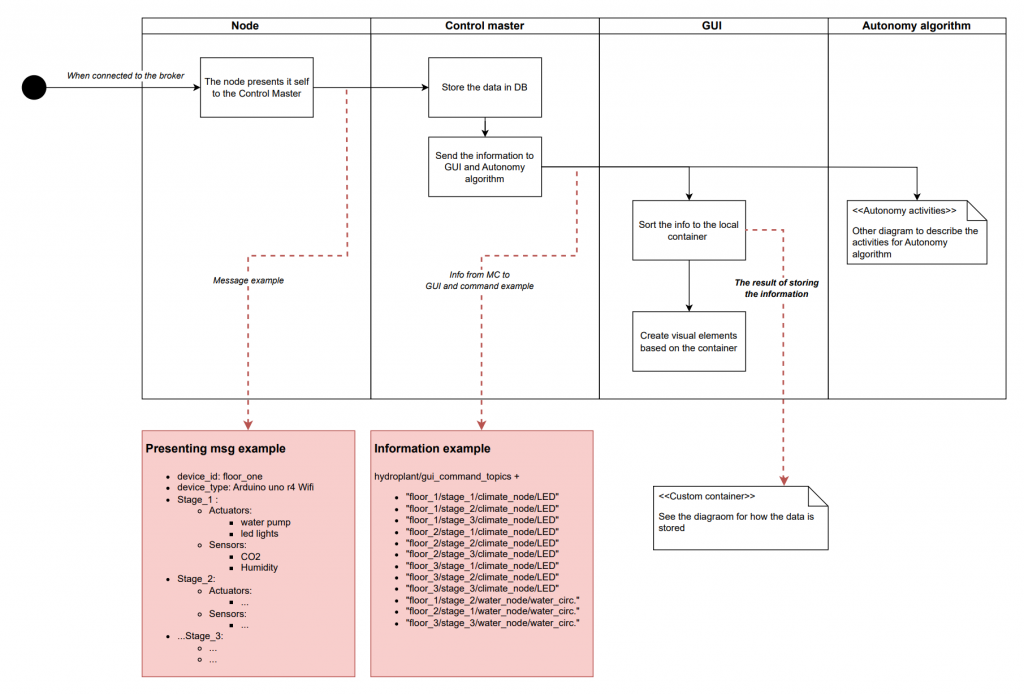
The custom container is locally stored in the GUI device. After sorting the information, we dynamically allocate the objects and inserting them to the Custom container. The GUI uses this information to make layout and visual elements that the GUI operator can interact with. The container has several use cases:
- Interaction: When a button/switch is clicked on, the element finds its “address such as Floor_1/stage_1/water_node/actuator, and sends the command to the right destination, and updating it the actuators state.
- Synchronization: master controller can request to change the state of an actuator in the GUI, then both the container and visual element will be updated with the new state.
Additional key words such as “Hydroplant/gui_command/”, and “Hydroplant/gui_command/receipt” is added globally to distinguish between different request to the system.
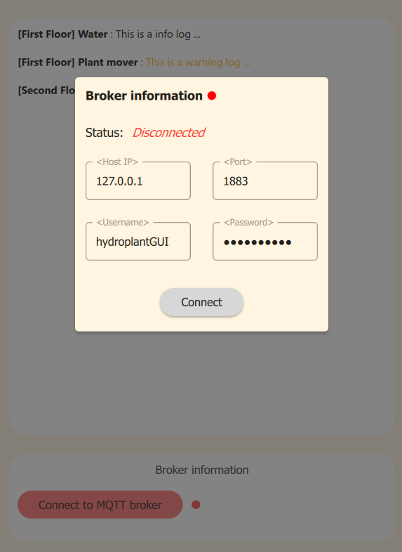
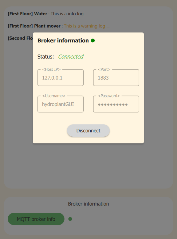
Popup panel broker information
Created a popup for connecting the GUI to the broker with necessary information, and viewing broker information when it is connected. The popup has two states:
- When the broker is connected
- When the broker is disconnected
You can see the difference between them in the pictures below.
Refactoring and Documentation
I have also refactored some of the code i wrote last week to make the main.qml clean and seperated the section codes such as left side bar to seperate file and referring to it as a custom component in the main.qml file.
I have tested out some different documentation tools for documenting the GUI and to be able to automatically generate an HTML file. Since the GUI consists of C++, QML, and JavaScript files, the best option i have found yet is Qt doc. I will set up the documentation in the following weeks.
Loging in the GUI
I have also added functionalities for logging with different levels: info, warning, and error. I have created a interface for external loging such as from different nodes(microcontrollers) and Master Controller, and one internal interface for the GUI. The internal log interface is tested, but, and we will test the external interface next week. This is an important functionality when we are testing the whole system, since we have to test the interaction between several devices and applications it is essential to have a logging panel one place to track the behavior of the whole system.
Micro controller
Testing MQTT communication with Oscar as he has described bellow. Added new functionalities to the Micro controller Library together with Oscar:
- While the micro controller making the message to present it self, it also subscribs the topics it needs based on the actuators, sensors and logic controllers it has in order to receive commands from outside.
- Implemented the new format a node have send when it presenting it self.
We have also desided the format of message exchanges for commands and logging between devices which will follow a JSON structure.
Commits
Only users who are a part of the GitHub organization can see these commits.
https://github.com/hydroplantno/library/commit/902aaf7f27805f7f6d0c46ca8ff9d612c3727615
https://github.com/hydroplantno/library/commit/ef110031ae9ad066d6173d379ae0737fa2fdf939
https://github.com/hydroplantno/mqtt-nodes/commit/bb8d281c633dbaafffb2bec3d7b261b2182f2057
https://github.com/hydroplantno/mqtt-nodes/commit/70dcd2dee2abff348dc9a7e26b6d4fd47518e9a9
https://github.com/hydroplantno/mqtt-nodes/commit/21c9d5471ce7e317e8b454705b0aaad5a10fd50d
https://github.com/hydroplantno/mqtt-nodes/commit/0f9bb503194680fb036c75025fd20dc8f4da42d8
Oscar Melby
Moved GitHub actions runner
Decided I wanted to move the self-hosted runner for our GitHub actions from the Pi to our LAMP server, which also hosts our website. Wanted to do this since the Pi was quite slow to carry out the jobs, but mainly the program would die after running for a while (I think). Could immediately see that the GitHub checks ran much faster, and I hope it will continue running for a long while, so we can just forget about it and focus on just programming.
MQTT Communication
Debugged together with Shahin. Decided we had to change the package we used for communication from ArduinoMQTT to pubsubclient due to their weird design choice, and how our code is structured which led to us essentially not being able to read message contents without doing some weird C++ gymnastics or refactor everything we previously had made.
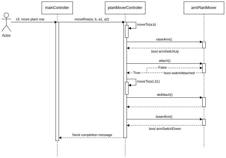
Got communication to work, so we can send a command from our GUI to our master-controller and then to the Arduino which actually carries out the action.
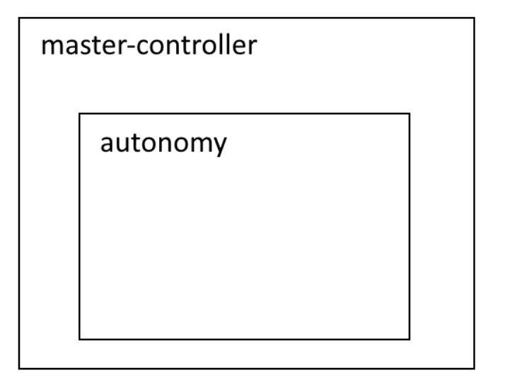
Setup autonomy
Wrote a small proof-of-concept for our autonomy which shall control the whole system autonomously, but have yet to test it fully. The design we currently want to have is that the master-controller handles all communication and has the “bigger-picture” overview. So master-controller receives and sends messages over MQTT, handles the database connection, and saves the current state of the system. Autonomy lives within the master-controller and wants to know some data, but not everything. It shall also be able to communicate using master-controller’s connection.
Commits
Only users who are a part of the GitHub organization can see these commits.
https://github.com/hydroplantno/master-controller/commit/7ef0c9675ecd6f9c4d375db741a014deb061ac5d
https://github.com/hydroplantno/master-controller/commit/2632c038041c594eb74347a1baafc8e077427559
https://github.com/hydroplantno/library/commit/1ede63daa813b286d0fc1fd19887e14fb6a12ab3
Aditi Deshpande
This week I mostly collaborated with Theo. I sadly had a lot of problems with building my program with PlatformIO, it was trying to find the platformio.exe file in the wrong path and spent almost 3 hours trying to find the problem. After a nervous breakdown and some cursing, I kind of found a way around to build it by running it through the PlatormIO command line interface, so I can build my program now but I will fix the problem hopefully by next week. I also set up Github and my branches in Visual Studio Code which also took quite some time.
Update: I have gotten PlatformIO to build properly. There is still probably a bug as I had to change the path of Project_Dir to the path where the .exe file is so as a result when I create a new project it saves it in the actual folder where the .exe file is, but I think that it’s not going to be a very huge problem. Also, I made a very simple Arduino program and tested it to make sure the program uploads the code, and it does, so, huge relief.
What to do next week:
- Make sure the mover class works as it is supposed to do. Eventually move over to buttons and test if the stepper works with buttons ( which will act like switches).
- Figure out about how the switch will be connected, and see if possible how to code it
- Make the Plant Info Node(PIN) if possible, and figure out how to connect the camera.
Collaboration- Aditi and Theo
As the plant information node and plant mover controller will have the same functionality when it comes to moving to the correct stage and place, we decided to work together. We have made a class called Mover which has the Go_to function responsible for moving the units. We made a class diagram, which looks like this:
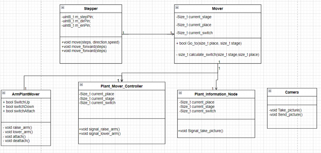
The function Mover::go_to(u_int32_t place, u_int32_t stage) is a member function of the Mover class. Its purpose is to move a stepper motor to a particular target location identified by a switch. It takes two parameters: place and stage, which are used to calculate the target switch with the calculate_switch(place, stage) function. The go_to function works by continuasly moving the unit until it activtes the correct switch, the switches has not yet been set up, therefore we are using millis() to test the code.
bool Mover::go_to(u_int32_t place, u_int32_t stage){
    u_int32_t target_switch = calculate_switch(place, stage);
    u_int32_t counter{};
    auto lastTime = 0;
    u_int32_t interval = 5;
    bool on{1};
    auto millistohours = 3600000;

    while(on == true){
        if(get_current_switch() < target_switch){

            if((millis() / millistohours) >= (lastTime + interval)){
            lastTime = millis();
            m_myStepper->moveForward(1000);
            counter++;
            if(counter == target_switch){
                on = !on;
            }
          }
        }
        else if(get_current_switch()  > target_switch){
            if((millis() / millistohours) >= (lastTime + interval)){
            lastTime = millis();
            m_myStepper->moveBackward(1000);
            counter--;
            if(counter == target_switch){
                on = !on;
            }
        }
    }
    set_current_switch(target_switch); // set new current switch
    return 1;
    }
}

u_int32_t Mover::calculate_switch(u_int32_t place, u_int32_t stage){

    for(u_int32_t i{};i < plant_info.size();i++){
            if (plant_info[i][0] == stage && plant_info[i][1] == place) {
                return plant_info[i][2];
            }
    }
}
The rest of the mover class, the header file and other functions can be viewed at this GitHub link :
https://github.com/hydroplantno/library/tree/aditi-theo/mover/LogicController/Mover – Connect your Github account
We tested this code by connecting the arduino with the stepper and we encountered some problems along the way: The millis() functions becomes a very big number very quickly, but our most recent commit should have fixed this, and we will test again next week.
Theo Magnor
This week has been spent on refining and creating diagrams, designing and coding a mover class together with Aditi. This class contains the logic for controlling the stepper motor that moves the plant mover and plant information node. We have also spent time testing this code.
Diagrams
Refinement of the activity diagram showing logic behind moving one plant row from a to b:
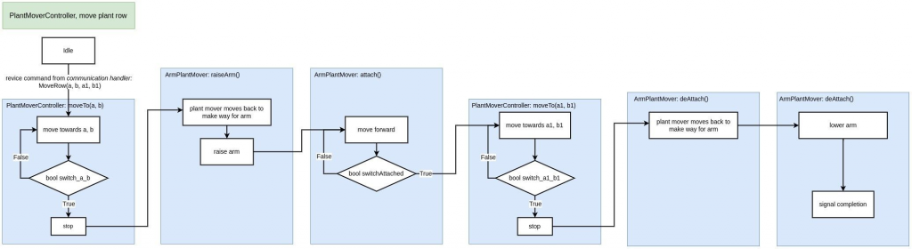
Also designed a sequence diagram showing communication between the components of the plant mover:
Ivan Bergmann Maronsson
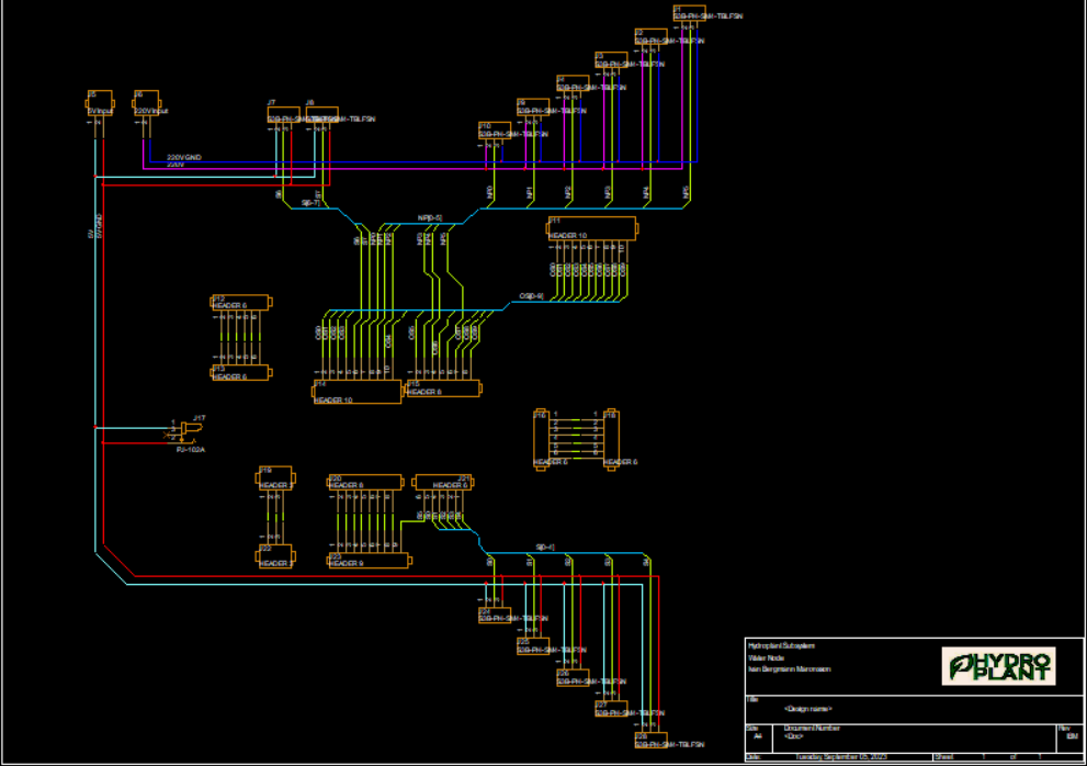
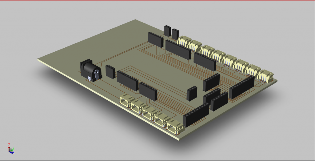
This week has been spent on finishing up the main components on the PCB, fixing the schematic I made last time, and adding a silkscreen layer on all my components so that I am able to simulate the PCB in 3D. Now we just have to add more smaller components. This being diodes, LED’s, resistors, and capacitors.
This is the schematic after some changes, and there are more to come.
And this is the current 3D model of the PCB.
Have a lovely week with smart systems!