Introduction to This Week’s Update on Smart Systems
Every problem is just an opportunity waiting to shine! We’ve had quite the week—filled with endless coffee, passionate debates, and the rhythmic tapping of keyboards. From drawing to drawing, component to component, and debugging session after session. And after all that, some things clicked, while others… well, they’re taking their sweet time. But don’t worry! As they say in the world of smart systems development:
If at first you don’t succeed, it’s probably a bug.
– Could not find the author, but We’ll get there!
Enjoy your readings from our beautiful members!
Shahin Ostadahmadi
GUI Requirements
Short Description and Qt Quick:
I’m using the Qt Quick framework to design our application. I use C++ for the backend logic, QML for the visual frontend, and JavaScript to handle some component logic.
- Layout:
- The GUI should have a structured layout, organizing visual elements into distinct sections with boundries and adjustable size when the window been resized by the user.
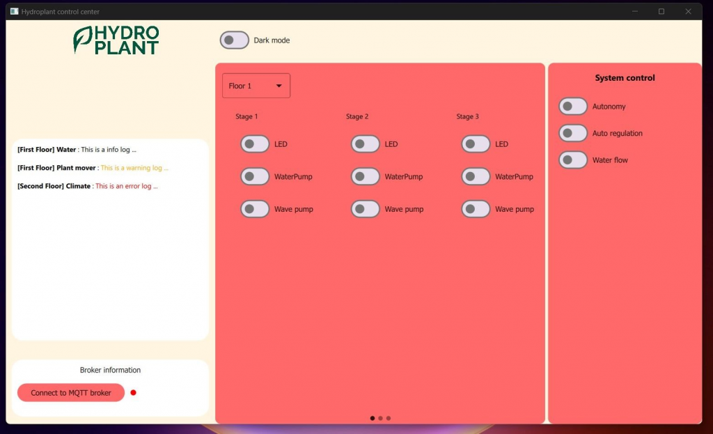
The layout is designed with a standard structure:
- Left Sidebar: Features the logo, device logs, broker information, and other essential details.
- Upper Sidebar: A dynamic row that houses various buttons and information, including the Dark Mode toggle. Items adjust their alignment and size based on the layout.
- Right Sidebar: Contains critical system control elements. Users must confirm their choices due to the high impact of these controls.
- Center: A swipe view that allows users to navigate between different action and information pages, like floor actuator controls or light calibration settings. The current view is set to control floor actuators, with a dropdown menu for floor selection (defaulted to floor one).
- Colors: Visual elements follow a global color palette defined in a config file, ensuring consistent aesthetics throughout the app.
- MQTT Interface:
- Implement an MQTT interface to facilitate communication with the Master controller and other system components.
I have set up an MQTT interface to connect to the broker, and testing was successful in communicating with the control master. The setup required a C++ class to handle the MQTT client and exposed the MQTT object to the application environment. This ensures that all the visual elements and backend logic controllers use the same MQTT object.
- Data synchronization:
- The data displayed on the GUI must always reflect the current state of the system
The diagram below shows how our system is influenced by two main entities: the GUI (utilized by operators) and our autonomy algorithm. For seamless operation, it’s essential both have the latest data reflecting the system’s current state.
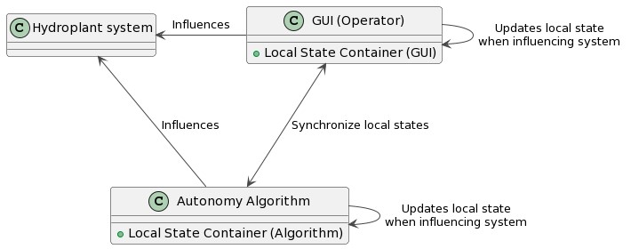
To ensure this, the GUI has to fulfill these requirements:
- Custom Container: The GUI should employ a custom container that represents the actual system with data synchronization functionalities.
- Immediate Updates: Any interaction with the GUI should adjust the state of the associated visual elements and send update info to the Control Master.
I have implemented a custom container that reflects the physical system and exposed this to the QML environment. As you can see the switches in the SwipeView image of the GUI, all these switches are created dynamically from the information provided by the container and they represent the actual system. Whenever a switch is toggled, the system does:
- Updating the container for the specific element (switch in this case)
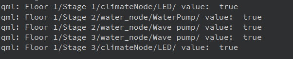
- Sending the command to a dynamically generated topic that the Master Controller expects.
- The topic follows this pattern: Floor_X/Stage_X/node_X/component
I’m printing the topic from the editor and you can see it follows the right pattern.
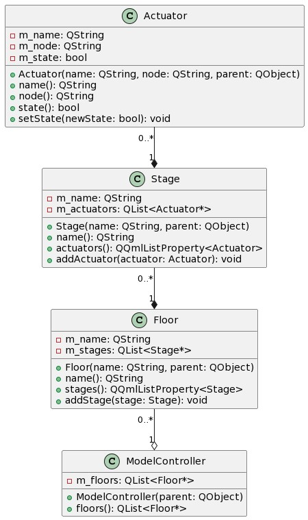
The diagram below illustrates the structure of the container. The Model Container is where we define the objects that exist in our system and it is been exposed to the QML environment with all the information it has about its content. The only component that is not implemented is to functionalities in ModelContainer to take a list of floor objects, not just one, and its QML functionalities to be able to iterate over the list of floors in the QML environment. All other functionalities are implemented and tested.
- Initialization:
- Upon successful connection via MQTT, the GUI should introduce itself to the Master controller.
- It should then request configuration files (including actuator states, logic controller settings, and sensor calibration values) and auto-update its state container.
The introduction part can be done statically for now, next week I will implement that it introduces it self dynamically. The Master Controller will then be able to detect if we have visual elements that not representing the system or if we miss some components. Implementing the request for configuration files will be within the next two weeks.
MQTT test page
Created a page for testing the MQTT connection. We use this page to test our different MQTT interfaces on other subsystems. From this page, we can send messages with various data structures to a specific topic and see if the receiving subsystems handle the information properly.
Arduino Microcontroller Requirements
This week I have been working with these Arduino requirements.
- MQTT Connection:
- The Arduino should establish a connection to the broker during startup. It should not proceed until a successful connection is confirmed.
I have implemented the MQTT communication interface, and along with Oscar, we made the communication work after a while of failing and starvation. The implementation is merged into the Hydroplant Library, and I also updated some of the Library code with Oscar, we were happy to find some dangerous errors!
- Device Presentation:
- When successful connection, the Arduino should publish its identification details to the appropriate broker destination (handshake). This should include: Device name, Physical type (e.g., Arduino, Raspberry Pi), Actuators (list of IDs), Sensors (list of IDs), Logic controllers (list of IDs)
- The presentation information should be dynamically generated, identifying all active sensors, actuators, and logic controllers.
It is implemented and the Nodes (Arduino UNOs) represent themselves dynamically upon the connection with the broker.
- Message Distribution:
- The Arduino should actively listen to specific topics to receive commands from the broker.
- It must route these commands accurately to their intended targets, either actuators or logic controllers.
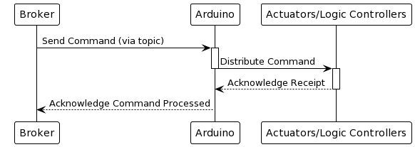
We ran into implementation problems, so we will be back next week with this implementation!
Commits/PRs
Only users who are a part of the GitHub organization can see these commits.
List of commits (all the commits is on my branch):
Library (from 25. aug) in Library:
https://github.com/hydroplantno/library/commits/shahin_mqtt_communication
Water_node and GUI, all the commits is noe
https://github.com/hydroplantno/mqtt-nodes/commits/shahin_comunication_mqtt_interface
Oscar Melby
Environment setup
Created needed GitHub repos and cloned them, also had to set SSH keys again after my last PC broke 😭 😭
Installed VSCode remote SSH server on the Pi to be able to develop remotely and run everything I need within VSCode, which makes life much easier.
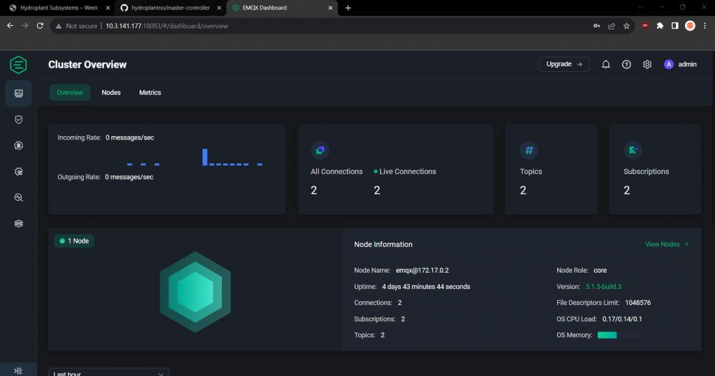
Installed EMQX docker container and got this running with correct ports and linking. This will be our broker or “server” which sends messages where they should be received. It is running on our Pi, where our master-controller will be located. EMQX also has a web interface, shown below.
Setup Black to auto-format on save both on the Pi and local PC.
Installed PlatformIO and libraries for communication such as WiFiS3 and ArduinoMqttClient
GitHub Actions
We want to have documentation, okay formatting, and a couple of other things that should be continuously updated when we make changes to our codebase. Since we host our code on GitHub, GitHub actions seemed like a logical solution. However, to automatically run processes when something in the code changes, I needed to set up a self-hosted GitHub actions runner, since to use GitHub’s runners you would either need to have: 1. a public repo or 2. pay a monthly subscription.
Added a yml file to our repo which should run on every pull request and checked if the formatting is correct. In the future, we want to have automatic building and uploading of documentation.
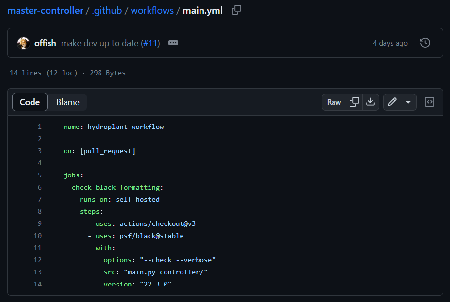
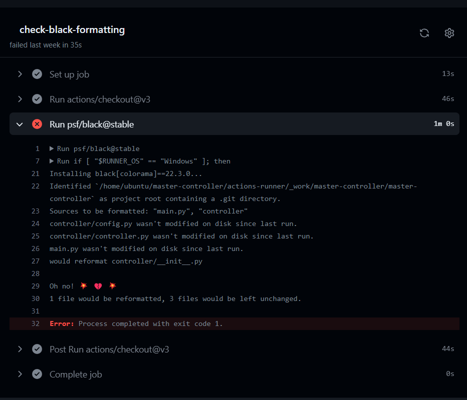
Below you can see the formatting check failing on a pull request, since __init__.py was not correctly formatted.
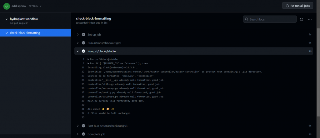
and a successful check:
Master controller
Our master-controller is the “brain” of the system, it will have control over everything happening and save data to our database, log important stuff happening, logic for our autonomy, and more. Master-controller sits on the Raspberry Pi together with our MQTT broker.
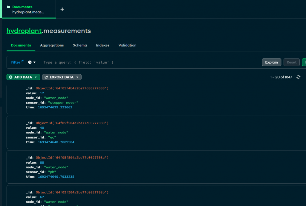
Set up and structured the master-controller and got it working with MQTT communication using paho . Also got communication with our MongoDB database working, so now every measurement sent by a node is processed by master-controller and added to the database.
MQTT communication
Learned about MQTT and got communication working, together with Shahin, from the node (Arduino UNO R4) to master-controller (Raspberry Pi) and vice versa. In addition, we got communication working from GUI (PC) to master-controller.
Within the next week, we should be able to send commands from the GUI to a node. If it should go through master-controller or directly we don’t know yet, this is a design choice we have to make. Our master-controller will contain the autonomy which MUST be aware of manual changes made.
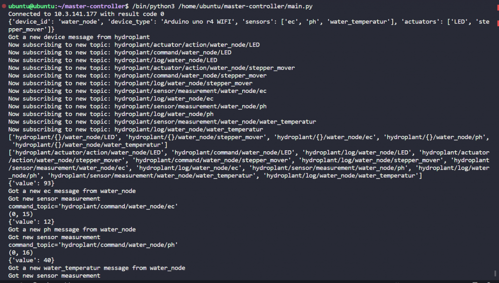
Here you can see the Arduino (node) connecting to the broker and presenting itself. The master subscribes to a bunch of topics and starts getting measurements from the node. The vectors are prints for when the master sends messages back to the node. Every time we get a measurement we add it to the database, but this does not get printed.
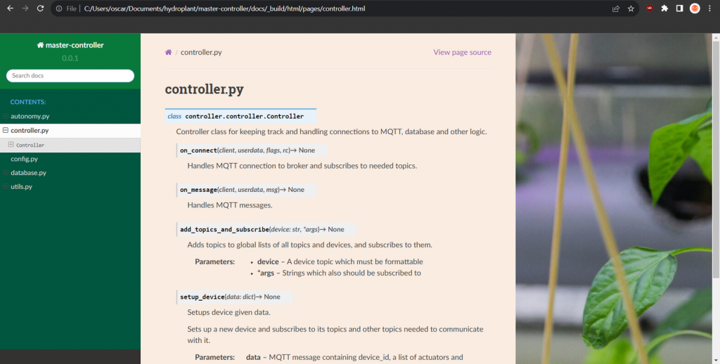
Code documentation (for master-controller)
Set up documentation using Sphinx for Python code which builds static HTML files from some reStructuredText files and docstrings in the Python code. We want to be able to upload the documentation automatically to hydroplant.no, but how we would do this with GitHub actions, I don’t know yet.
In addition to setting this up, I also wrote docstrings and documented a good chunk of the code.
Commits/PRs
Only users who are a part of the GitHub organization can see these commits.
https://github.com/hydroplantno/master-controller/commit/27b5e53a971ccd9027657adf2bc5174ab108730e
https://github.com/hydroplantno/master-controller/commit/31cc65bb711f4fb8a3a0c09c7612bdb11808bcee
https://github.com/hydroplantno/mqtt-nodes/commit/86722cbd2390cb6ea2a154a1aff4eda339a6df33
https://github.com/hydroplantno/library/commit/12ac8b039c9dfff2becdfb74456b34abff741297
https://github.com/hydroplantno/master-controller/pull/13
Aditi Deshpande
My technical responsibility is to design the Plant Information Node. These were the requirements:
| Plant Scanner / Plant Information Node (PIN) | Must be able to move from one place to anotherMust be able to capture images both day and night and send image dataMust have an interface for wireless communication |
|---|
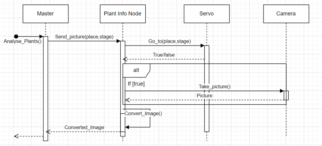
Based on the requirements, I designed an activity diagram and a sequence diagram:
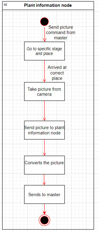
The activity diagram provides a very high-level overview of how the PIN is going to work. The PIN gets a command to take a picture of a specific plant holder, so the PIN has to go to the right place with the help of the servo and give the command to the camera to take a picture, convert the picture to how the master controller wants it, and send it. It is explained more in detail in the sequence diagram.
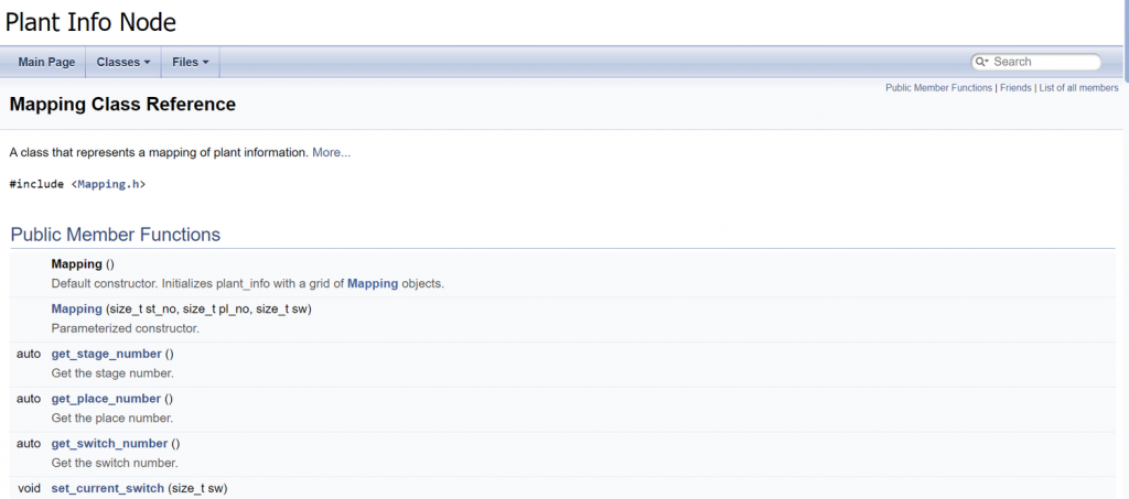
After designing the system with structural and behavioral diagrams, I figured that the next thing I needed to figure out was how to move the PIN to the right stage and place. So I decided to map the stage, place, and plant holder number( which will have a switch attached to it). I decided to make a mapping class in C++. The code has been pushed to GitHub and here is the link: https://github.com/hydroplantno/Utvikling-av-Smarte-systemer/tree/Aditi
I have also documented the code using Doxygen. The code needs way more functionality, but one has to start somewhere right?
What’s to be done next week from my side?
- Complete the Go_to function mentioned in the sequence diagram. I also want to connect the Arduino and make sure that the PIN will move to the right stage so as to see the physical results.
- Discuss with our team leader what kind of camera we want to connect to the Arduino and plan what that will look like.
- Discuss with our electronics lead about the functionality of the switch.
Theo Magnor
Setting up git
Setting up the git repo on my local machine and learning how to correctly manage branches and files according to the project standard.
Meeting with Shahin
Shahin walked me through how the existing system works and how it is set up. This was important for several reasons, it allowed me to create a subsystem that follows the same project structure and code standards. We also discussed technical requirements and specifications for the code I am creating, and the code will be used in an Arduino to control a servo. This servo is used to move rows of plants through the different stages of the system.
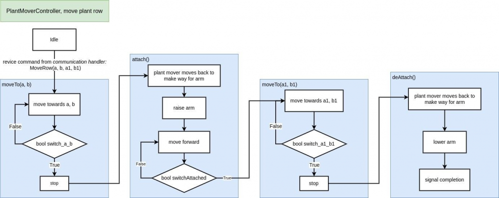
Plant mover controller
At each plant row, there will be a switch that signals to the plant mover whether it has moved to the correct row. There will also be a switch on the plant mover, to signal whether it is in contact with the row or not. Here is a diagram that describes the logic for moving a plant row:
Switches
The switches will use a controller that reads the values and outputs them to plantMoverController. Ivan is responsible for making this switchController, I have talked to him in order to make the interface.
What I need to do next week
- Further visualizing the system with diagrams. I want to show a more detailed and accurate view of the system.
- Talk with Ivan.
- Continue working on a code prototype for the Arduino.
- Learn Doxygen
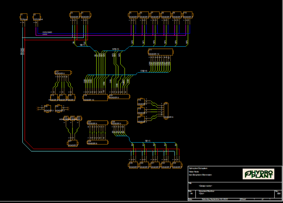
Ivan Bergmann Maronsson
This week we started to document what components the “Water Node” PCB needed and the requirements those components need to function properly for the system.
The components that we currently have noted, are 6 low voltage pumps, 7 high voltage pumps, 7 diverse sensors, some relays, and an Arduino R4.
Using the Arduino R4 gives us some limitations, this being that we only have 6 analog pins, 6 PWM pins, and 8 digital pins, with the trade-off that we are able to send signals wirelessly and that there is a programmable led matrix on the board. We are able to use the Arduino R4 because we are only going to need 6 PWM pins and 5 analog pins. Eventually, a MUX is able to be added to allow more components that either use PWM signals or analog signals.
With this in mind, we are able to design a PCB that “houses” the Arduino R4 and is able to use its pins for certain needs. This means that we are able to turn some of the pins we plan to use into JST connectors with the help of the Water Node PCB. The rest of the pins that are not going to be used are still going to be connected to the PCB where they can be used when needed.
Currently using Orcad to design the layout of the PCB and making custom components and footprints for specific parts, and or finding already exciting footprints and making basic components when needed.