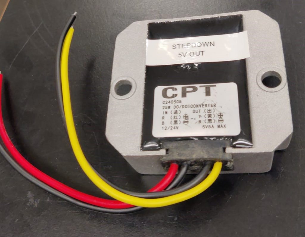
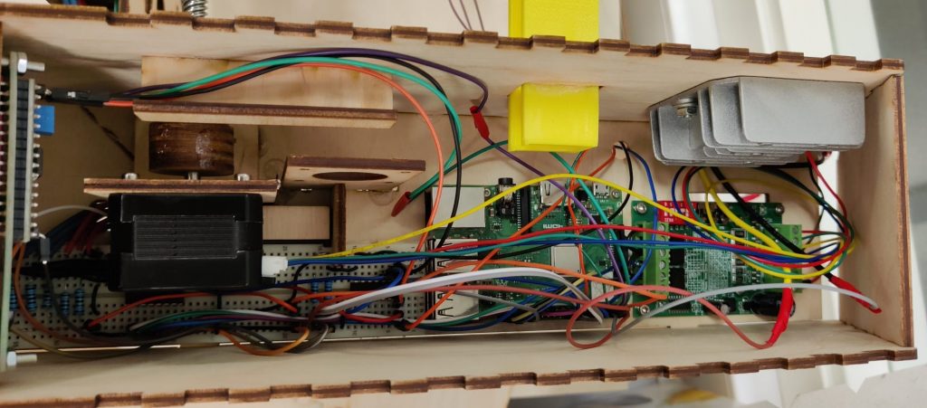
We got a stronger dc dc converter that also can work with 24v input, and it provides 5v with 5 ampere. With this, our rasperry pi powered up stable! A good side effect we found out with researches is that this converter provides short circuit protection, over current and over temperature protection and when the fault is solved it’s working again.
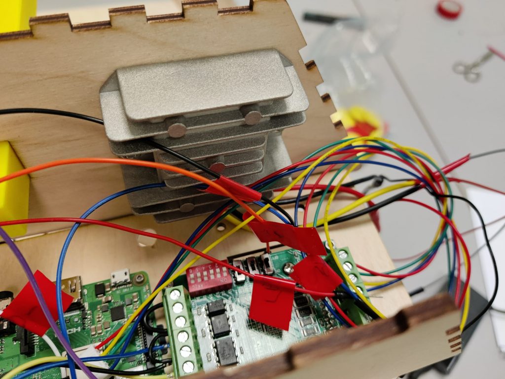
We spent much time on cable management and improving also this week. As we have moving parts (motor) and wires in one housing, we needed to make sure that the wires don’t loose connection because of vibration or contact with the motor or spindle.
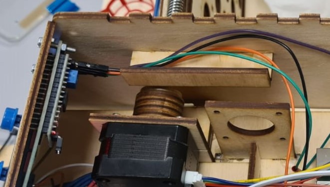
Especially we also added a cable canal into the housing that the wires from the LCD display cannot touch the spindle.
After making the little extended legs last week we found out that the legs were about 4 mm to short. This is because the plywood plate is bent. Also the plate was a little bit too thin, that is why the extended legs on the inside are now 3.5 mm (thickness of plate) shorter then the outside extended legs. With the new legs the coinslider is able to slide over the board nicely again with a consistent gap.
We glued the legs together and tested the machine. When we tried to align all the components and tried to get the coin pusher moving, we found out that the gears made a lot of noise and also got stuck sometimes. The problem was found quite fast. The hole in one of the gears was not perfect in the middle so we discussed with the hole group about that issue. The result was that with some testing oft the linear drive and the stepper motor we know that the machine is fast enough without that gear. So we removed the gear from the machine and designed an connector to directly connected the stepper to the linear drive.
The result was that the robot was a lot more silent but still fast enough. Just the motor was a little bit moving so we needed to design a construction to hold the motor in position but also giving him the space, it needs. In the end we tested it and now it worked as we have expected.
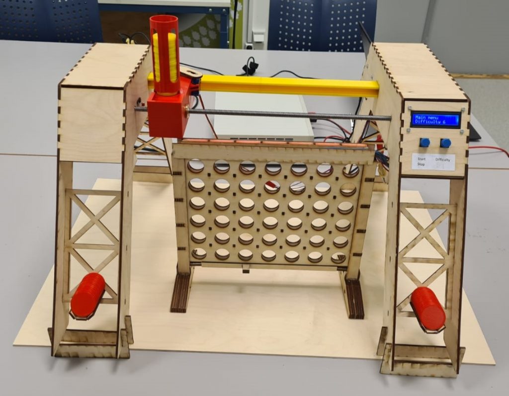
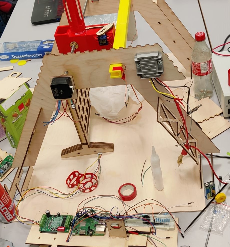
Now it was time to align all the components, the left tower, right tower, linear drive, rail and the gameboard and glue them together on the base plate. That part was important because we had to make sure that the coin pusher is perfectly aligned above each column of the gameboard so that the coin could fall into each column. Also the linear drive and the rail need to be aligned with the towers that it can’t get stuck and the motor can to turn the linear drive..
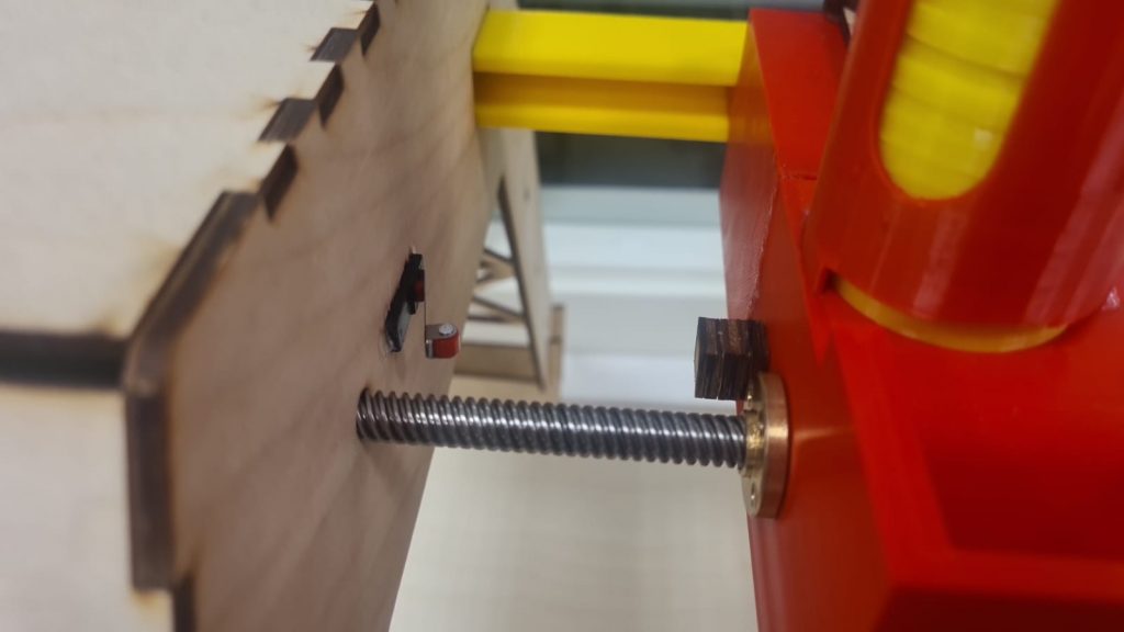
With all mechanic finished, we calibrated the nema motor. We need to control all 7 columns plus an init position. Therefore we also added an end position switch into the left “tower” of our housing. It’s a circuit breaker switch. It passes power through when the switch is opened but as soon you close it (push it in) the circuit get’s interrupted. Software wise we are driving the motor slowly towards the switch the first time we start the program (and maybe later also every game, we need to figure that out). That is implemented in a while loop. As soon as the switch breaks the circuit we are breaking the loop and stop the motor. That is now our init position from which we can calucate all positions for the game. As we are driving in the game mode much faster, we also move about 1cm away from the calibration switch and use this position as “sleep” / base position. With that we are avoiding crashing fast into the left housing as it takes some
    while GPIO.input(NEMA_STOP_PIN): # true if switch is open
        GPIO.output(NEMA_STEP_PIN, GPIO.HIGH)
        sleep(NEMA_SLOW_SPEED)
        GPIO.output(NEMA_STEP_PIN, GPIO.LOW)
        sleep(NEMA_SLOW_SPEED)
For calibrating the driving to the colum positions, we are using for loops. We printed out the number of runs of the for loop that it needs till reaching the desired column. For example for the first column we needed a range of 1110, starting from our “sleep” position. We figured out all positions. A funny fact is that driving between 2 nearby columns you need exactly 1000 loops. With that, calculation also got easier for all column positions.
For optical reasons, we also added two wooden covers to the gameboard. They are covering the photo resistors and its cables and also the LED stripe on the other side. As the cables 8 cables from the photo resistors were also loose, we aligned and glued them to the board that the wooden cover is laying flat on the gameboard and can be glued properly.
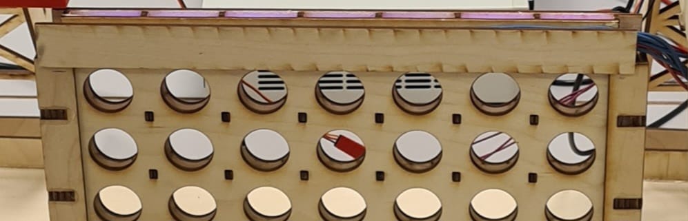
While playing the game, we found out that sometimes, but really rarely the coin from the player didn’t got detected. One time it was because the wifi connection to the PC got lost. For fixing that we run the our program in the startup file of the linux os. But still one more time a coin wasn’t detected. We monitored the photo resistor values and found out that in 2 columns, the values didn’t went that much down when placing a coin in front of the sensor. On closer inspection we have seen that the LEDs in this 2 columns are placed directly on the other side of the the resistor. Because of that it seems that the values don’t drop that much. We increased the detection value and now all coins got detected again. But after 2 games now a coin was detected software wise that wasn’t placed. Only shadow of the hand above seemed to trigger it. The new solution: a variable threshold for all 7 columns.. As it was already really late we decided to do this improvement, and also some other software optimization (there are several delays that slows down the program unnecessary for example and better user-friendliness) and little hardware tweaks (some hardware stabilization, coin box that you don’t loose them and some labels for input voltage, project name and button labels) next monday when also preparing the presentation for tuesday…