This week we tried to get the coin detection working. Remember the technic: Above the upper row of the game board, on one side every column has a photoresistor in the wood and on the other side there is the led strip incorporated. The photoresistor emits a different resistance depending on the light intensity received. With that we can detect if a coin gets dropped into a specific column as the resistance value will change in the time the coin is blocking the LED light.
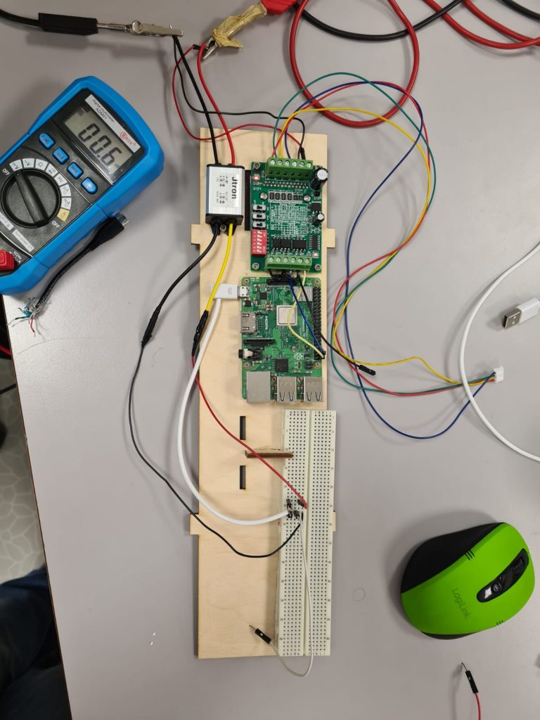
The rasperry pi has only digital pins, no analog ones so an exact value cannot be read out. A digital pin at the rasperry pi outputs high if the voltage rises over 1.6v. Our conclusion was: below 1.6v means low. So we thought that we could add some resistors with different ohm values in the photoresistor circuit so that the get a “high” signal if no coin is detected and if a coin is in there the resistance is rising and the voltage is dropping below 1.6v and raspi detect “low”. For getting the values we used a multimeter.
It was really difficult to find matching resistors. Also the rasperry pi often didn’t detect the change from high to low. We experimented a lot, also with the light brightness, light color, and the coins. One big thing we found out: The yellow coins don’t work for the detection as the they are quite translucent. That means the change of the value was about nothing! So the decision: player uses the red colored coins. With that there is a good change. About 0.3 v. Also the light didn’t do much difference in which color. We decided using red as the coins are also red. Then we can also use the LEDs as indicator whose turn it is. After we had everything just perfect setup, having a good voltage drop and also over the threshold 1.8v the problem: still the rasperry didn’t detect the change reliable! Big issue! We researched and found out a major problem with the high and low values of the raspi:
| Binary Logic Level | Worst-Case VI Voltage – BCM283X | Worst-Case VI Voltage – BCM2711 |
|---|---|---|
| Low / LO / 0 | VIL ≤ 0.9 Volts | VIL ≤ 0.8 Volts |
| High / HI / 1 | VIH ≥ 1.6 Volts | VIH ≥ 2.0 Volts |
“Worst case” means that for any input of VI ≤ 0.9 Volts (0.8 V for RPi 4B), that input will always be seen as a logic
https://raspberrypi.stackexchange.com/questions/29918/gpio-voltage-thresholds0. In other words, you shouldn’t count on 1.0 V input to be recognized as a logic0/LOW… it may be, or it may not be! Similarly, an input of VI ≥ 1.6 Volts (2.0 V for RPi 4B) will always be seen as a logic1/HI. Any value of VI falling between these limits is indeterminate.
That means in short. The high and low detection cannot be trusted between 0.9 and 1.6 volts and we cannot use it. All the work with finding right resistors and get it setup good: for nothing!
Possible solutions:
1) Using an analog to digital converter. There are some and this is our prefered solution as we also get real analog values and can use them for setting a good threshold value from where a coin is detected or not. We need to ask Zoran if he can give us one. An MCP3008 has 8 channels for detecting and we have 7 photoresistors so this IC seems to be the best option for us. The comminication between this adc and the rasperry pi is over an spi serial bus, which greatly the rasperry pi offers.
2) adding a capacitor to the circuit. Send a real short voltage to the pin to load the capacitor and then measure the time it needs until the pin detect “low” again. This is also not that accurate as of the problem that the high / low state is not that predictable in the middle voltage range.. So we would prefer solution 1 if we can get an adc!
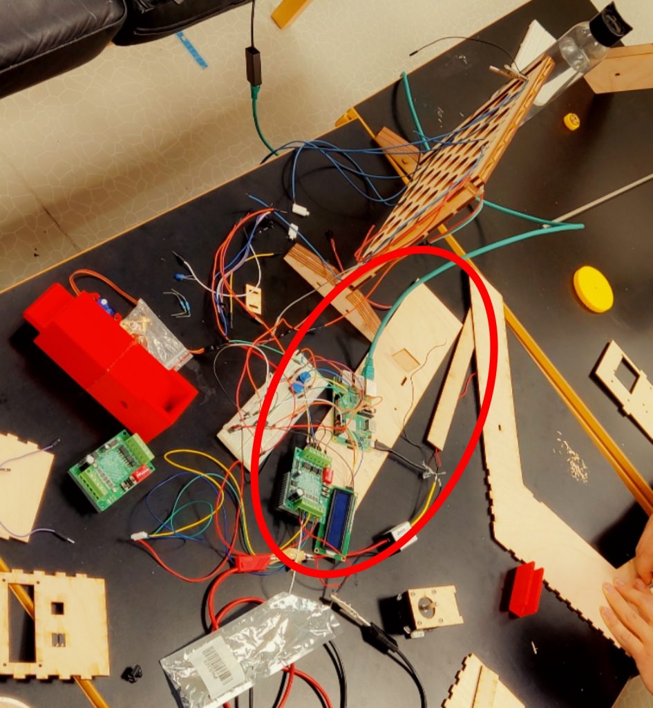
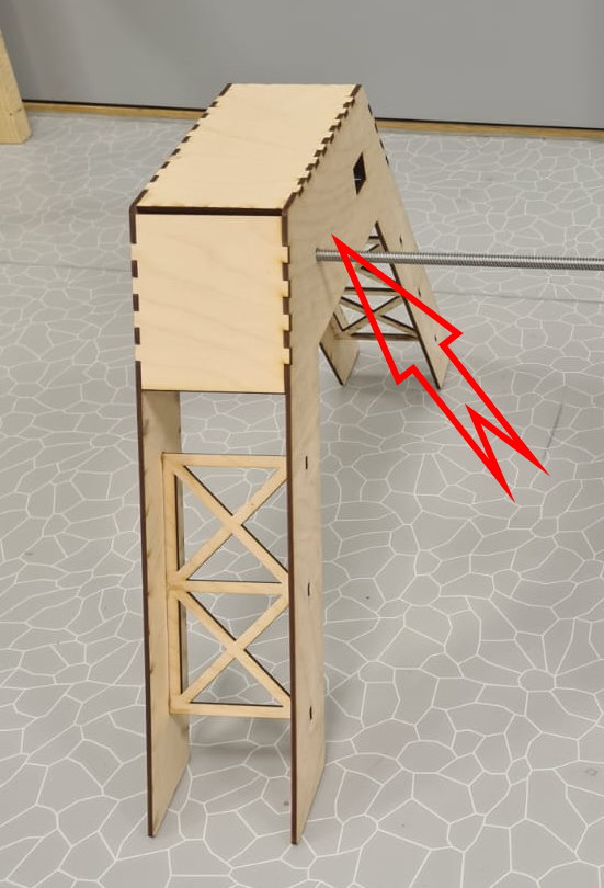
Also we used the cutted out base plate to try to figure out how we align all the electrical components, including a whole breadboard on it. It will be all hidden inside the stands of the game (see pictures below)
We found out a problem with aligning. The microusb cable going to the rasperry pi is too long and cannot be bent 90° at the beginning because of a hard protective cap. But that needs to be because otherwise the rasperry with the cable wouldn’t fit into the housing. So Zoran gave us another cable where we could remove the cap and also solder directly at the microusb plug. We will pimp this cable next week to make it working with our game housing…