Computer engineers
This week we fixed some small problems with the UI. Now that everything was setup we focused on the html code and the CSS code. Here is a little video showing our app.
HTML code
In order to have different pages we made several html files for each function of our system. So came up with 6 different functions, “Borrow Item”, “Register Item”, “Search Item”, “About Us”, “Contact Us” and we also made one for “Donating”. To divide each function we decided to have one html file and one CSS file for each function. Here is a snippet of “Borrow Code”.
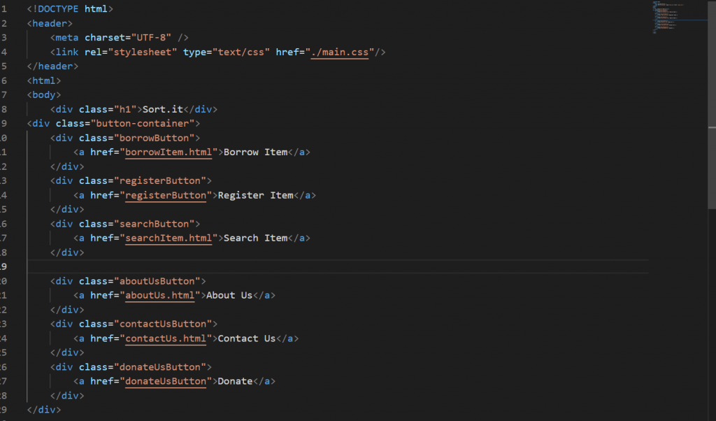
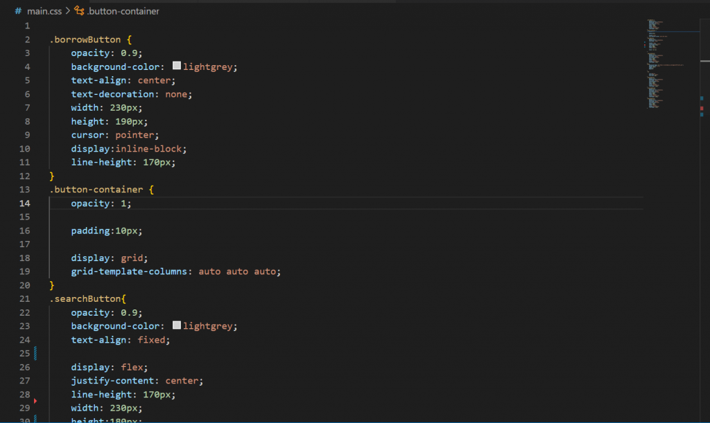
The html files were great write even though we sometimes faced some issues but the hardest part was the CSS files since everything had to fit perfect with the touch screen and till this day we are trying to match every page to the touch screen for raspberry pi. Here is a small snippet of our CSS code for borrow html file.
Mechanical engineers
This week I painted all the 3d printed parts that wasn`t black and the plywood. We want an all black modell. This contributes to the system’s aesthetic design. Aesthetic design is not a functional requirement, however it will make a significant impact when the prototype will be presented or put on display.
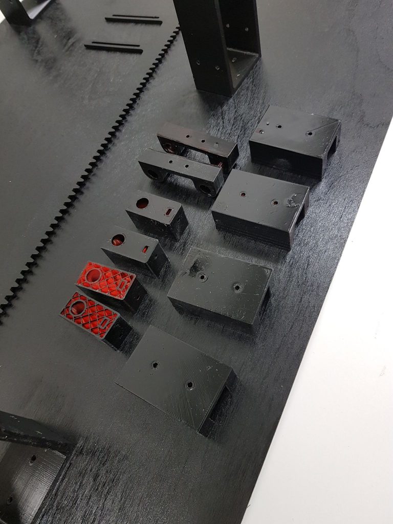
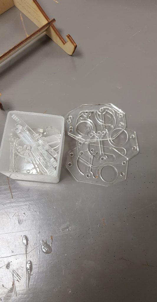
The group has worked hard now in over 10 weeks. We can finally see some progression, therefore i cutted some plexiglass in the lasercutter so we also could have a cool design on the claw.
Another ting I did this week was assembling all the claw/gripper parts so we have a complete claw/gripper. This took some time because we needed washers between some parts, due to too much friction between the surfaces of the joints.
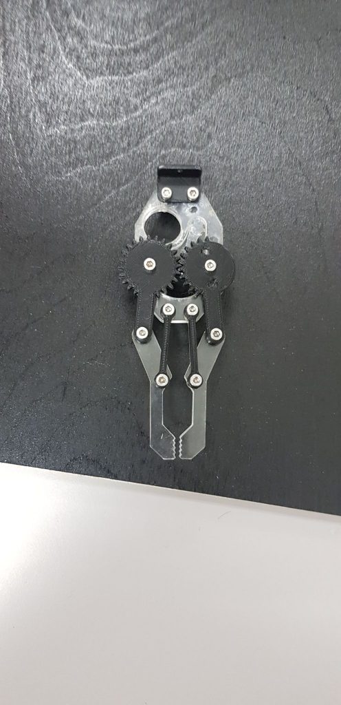
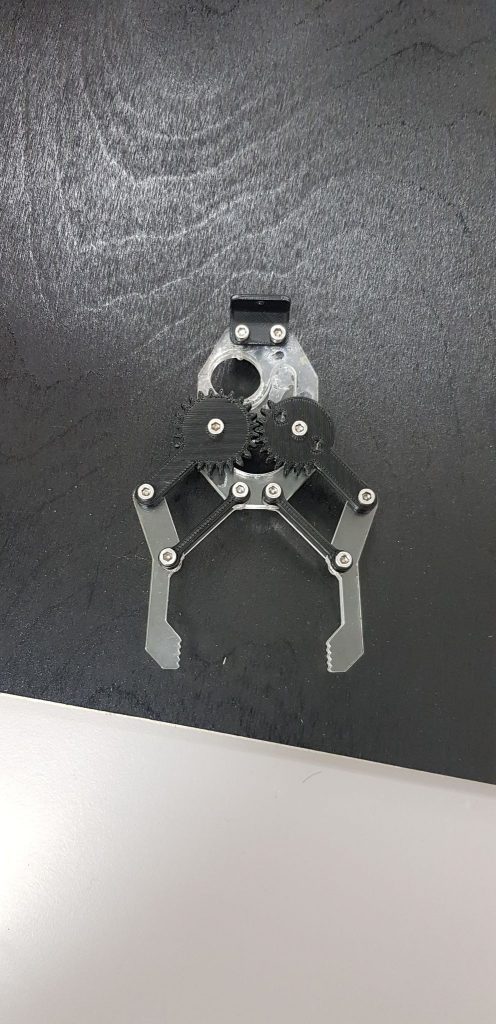
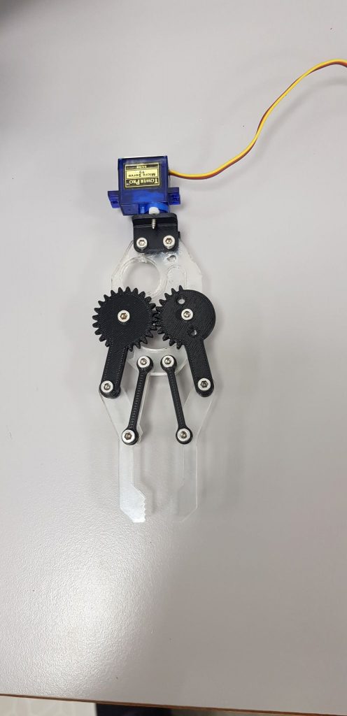
I installed the upper micro servo motor on the claw aswell. So it can move 180 degrees around z-axis. Still missing the second micro servo motor, but as i worked on the wheels and gears i noticed that the gear must be redesigned because its a little to small. It will probably work, but its better to have good gears for the function of the gripper. Also it will be easier for the micro servor to drive the gripper.
– Kim
Primary Assembly
This week the primary mechanical objective was to completely assemble the most basic structure of the system, meaning the components regulating movement in the x and y axis. A large amount of parts were sent to Kim and some larger elements were sent to Richard last week. Kim managed to print all the required elements this past weekend, printing around the clock, so we could begin the final assembly of the model.

Construction
During construction many minor faults in the parts were discovered. Not all the parts had been modified in order to be accurate after being 3D printed. This is due the various settings used on the printer, and 3D printing as a production method (measurements on the models must be modifed to print the part accurately and correctly.) Much time was therefore spent sanding down parts to ensure a perfect fit with the purchased parts and other elements.
Interfaces
The interfaces between mechanical elements are critical to the accuracy and function of the design. The interface between the claw/gripper and the z-axis glider(tool block) was not present this week, as we wanted to see physically how large the gripper would be when assembled compared to the rest of the assembly. I then designed a bracket which functioned as an interface between the gripper and z axis glider (part of the mechanism regulating movement in the z-axis) to be printed for next week.
In addition, the z-axis glider had not been correctly dimensioned, causing a lot of slack on the z-axis mechanism. The z-axis glider was therefore redesigned to have smaller holes in the glide-direction, as to ensure the axiis between the holes of the glider and 6mm guide shafts were colinear.
Further complications arose when testing the movement regulated along the plywood rack (y-axis). In order to function properly all respective axiis must be perpendicular to each other (x must be perpedicular to y, etc.) It was challenging to get this right during assembly. The carts (with ball bearings) gliding along the axis would stop due to friction. After much trial and error together with some rough measurements, I managed to align both shafts in the y-axis completely parallell to each other within a tolerance of a couple millimeters. This meant we were still having some trouble with friction. We considered whether the friction could be negligible enough for our system to function. We weren’t exactly sure, as we hadn’t tested the system with the stepper motors yet. We therefore decided to make a contingency part in case the cart with ball bearings added too much friction. This part was designed to just lay freely on top of the shaft, allowing some leeway in the x-direction to eliminate friction.
The systems most basic elements can be seen assembled below


– Ole Markus
Electronics
This week I was sick, so I continued drawing the wiring diagram from home. With the wiring diagram, it will be easier for me to wire up all the components after we are done with the prototype and we know which components we decide on using. It will also give me a better overview of all the components. I’m using a program that’s called Fritzing, and I am using the breadboard view as it is very easy to see which component is what. This won’t only make the job easier for me, but if I am unavailable, anyone in the group can understand how to wire up the system or look for loose wires and such.
– Mathias