Testing code together
This week we also thought that we should start testing the motor code, led screen code, button code, and the servo motor code all together so that we could see that it worked together. Obviously we faced some problems both when it came to code and electrical issues. So we tried to do some troubleshooting and isolating the problems and we thought that the servo motor was the problem. For some weird reason it did not act as planned when it was connected together will all the other components. I had to connect to my arduino and try to find out the issue but it worked perfectly fine on my arduino so I thought that it might have been the arduino pins so we had to change to digital pin 22. Which was good idea since the usual pins that we used on the sides were almost fully covered. We were hoping that would fix the problem but for some weird reason it now took a lot of voltage from the arduino and it only went one direction and made the claw grab hard. At the same time the led screen started dimming. The next day when we tried to connect the components again together it worked normally so we think that it had to be some electrical problems that we did not notice before since we were tired.
Some challenges were faced when connecting all the components we had worked on individually together into one system. One of these issues were with the pin numberings, and the number of pins available. We eventually realized that we have more pins available on the Arduino for digital read / write than we initially though, and so the problem was solved.
The power issue
When connecting the gripper component, the Arduino started to struggle with delivering enough power, and so the LCD screen started flashing. We solved this problem by connecting a secondary power supply to the gripper motor. This will be solved better in the future by using a motor driver connected to the main power source.
Calibrating gripper function
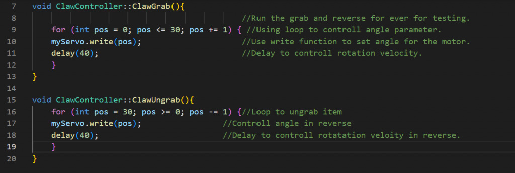
Since we delegated tasks last week my job was to program the gripper function so that it had the method “ClawGrab” and “ClawUngrab” methods. Before both of the methods were integrated in the same function but now I calibrated it better and in the same time made two different methods so that the methods could be called when the need for grabbing an item was there or ungrabbing an item if that was necessary. Here is a small snippet of my code.
Creating item class
This week we also thought of creating the class for the different items that were going to be registered in our sorting system. Since we now had many classes me and my collegues thought we should start with folder structure for the different classes. One of the folders being “Controllers”. Since the name of the folder was my idea we will have to discuss more about this further next week. Since I am also new to big projects and havent done structural organization of class codes before I will have to investigate how to include those classes when they are inside a folder. Since I had some student council meeting and I had already spent a lot of time I decided to look into it next week.
While considering areas of the code the work on, I realized that we were still missing a way to keep track of the items in our sorting system. This is some of the properties of each item we though were useful to have:
class Item {
public:

private:
   String name;
   int id;
   Coord coord;
   int width;
   int height;
   int length;
};
Setting up raspberry pi
While installing the Raspberry PI software with Mathias, we encountered some issues with the screen turning dark when connected to wifi. Therefore we decided to wait until the installation of the Raspbian software to install before connecting to wifi.
This week we decided to setup the raspberry pi with the touch screen in case we were going to use it as part of our user interface. So we connected it up and we checked if it had UWF firewall installed and basic application so that it could be used for further use.
Mechanical
Today we had presentation together with other groups. Therefore it took some of our time we had available.
I have discussed and cooperate with Ole Markus so he can start 3D-print some of the parts in the sorting system that he have modelled in Solidworks.
Next up was to help a other group, “chess-board”-group.
Me and Marte in my class (mechanical) lasercutted some plywood for their group-project.
3D printing
Since we are going to print much of our parts in 3D modells i bought myself a own printer. Tought it would be good for the group and also for learning.
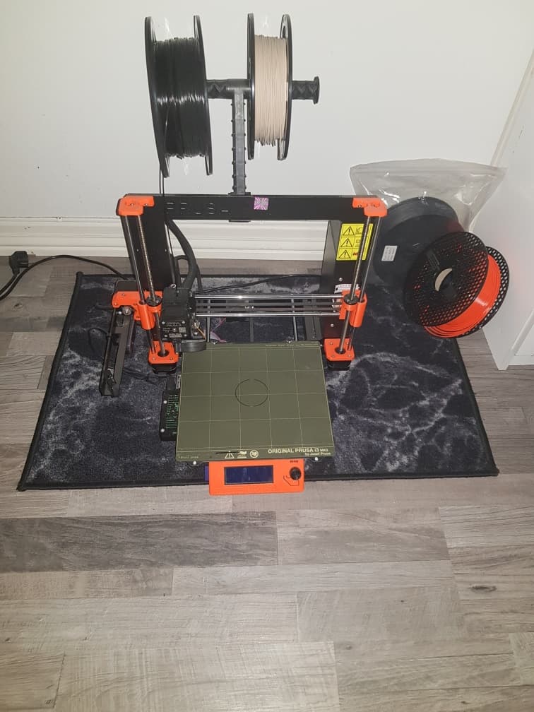
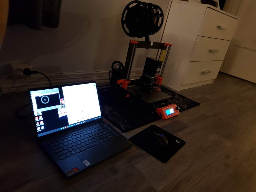
- Kim
Redesign
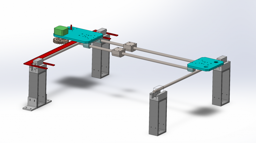
This week The primary goal was to finish the redesign of the rail system. Last week an agreement was made with supplier Richard that we would use linear shafts instead of aluminum extruded rails for movement in both y and x axis. The redesign of the system on SolidWorks was quite extensive as I aimed to create parts that could be modified for multiple types of rail carriages with different variations of rails. The platforms have such a large amount of holes to enable customizability. This entails we could use aluminum extruded railprofiles as a backup if the shaft system were to fail with regards to rigidity and/or friction.
Rigidity and friction were considered resulting in 2 shafts to regulate movement in the x-axis and 2 shafts to regulate movement in the y-axis. If we had used aluminum extruded railprofiles we could in theory only use 1 rail for movement in x and y respectively. See the picture below for the updated design with shafts instead of aluminium extruded rails.
Next week:
The plan for next week is to further design the central platform and movement in the z-axis.
– Ole Markus
Electronics
We have now decided to add a Raspberry Pi to the system which will be used with a touch screen to control the system. The Raspberry Pi we originally got from the teachers was a Raspberry Pi 1, but it wasn’t compatible with the touch screen, so we got a Raspberry Pi 4 instead, which was compatible. It took some time to figure out which cables had to be connected between a monitor and the Raspberry Pi, we got it running and figured we didn’t need the monitor at all. We inserted an SD card into the Raspberry Pi and installed the operating system so the computer engineers could start programming and make the Raspberry Pi communicate with the Arduino.
When testing the two servo motors we found a voltage drop of about 0.4 Volts when we applied resistance to the servo’s axle. The reason we measured to find a voltage drop was that there seemed to be a problem when testing the code. It seemed like the Arduino was not able to deliver enough power for both the servos and the other components, so we figured maybe we can try powering them with batteries. In that case, for the next meeting, we will need a battery pack to hold four AA batteries.
– Mathias