Date 21 Sep 2022
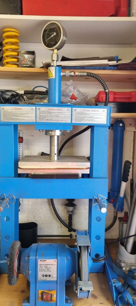
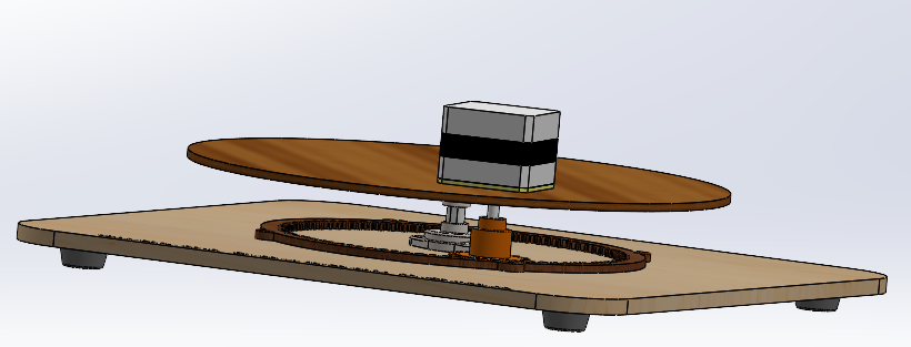
Two 3.5mm plywood plate was laser cut and bonded together to achieve the desired thickness of the base plate, the baseplate is kept in a hydraulic press between 2 solid plates of aluminum at 1 metric ton during the glue curing time to make sure is as flat as possible.
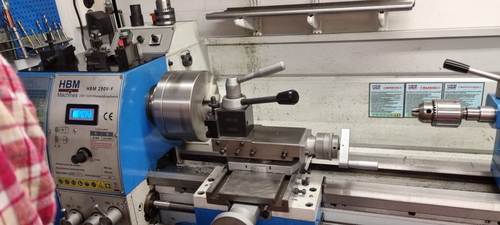
Shaft 8x40mm (item) between base plate and main board was manufactured in a lathe.
Instability between the two plates was detected during assembly of the two plates, the plates are supported by use of two bearings and a shaft. Root cause is that the bearing clearance allow misalignment between the inner and outer ring, the quick solution for this is to replace one bearing to half the undesirable play with a fixed support for the shaft in one end.
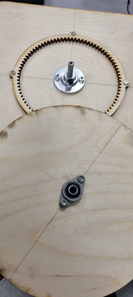
Main plate with ball gearing.
The bearing inner ring is equipped with a 3mm set screw to avoid rotation between shaft and bearing inner ring, the shaft has been machined with a flat spot to support this design. The same has been done at the base plate where the fixed support for the shaft is installed.
Conclusion: The modification done to the bearing assembly and use of hydraulic press during curing time on the base plate has improved the operating of the installation significantly and has to be acceptable for this material.
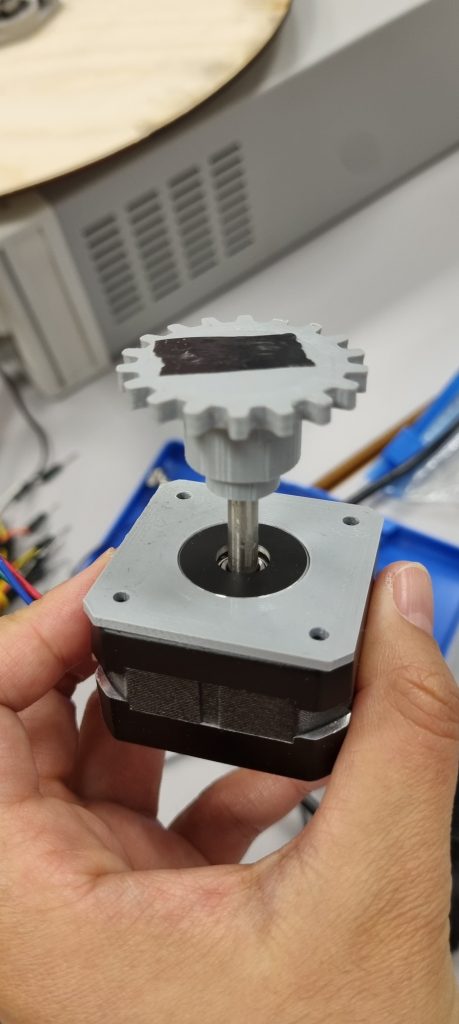
The step motor has arrived and the gasket/shim was 3D printed and installed, mismatch between the step motor shaft and pinion gear bore was detected during assembly and will be corrected by 3D printing a new interface between the two parts.
Work on the new step motor has begun. We connected it to the initial motor driver(TB6560 v2) which worked fine, but the motor couldn’t be controlled precisely. We ended up changing the motor driver with the L298N. After we connected the motor to the new motor driver, we tested it and everything worked fine. Then we had to find out how many “laps” (360 degrees) the motor has to make in order for the motor to do a full lap on the circle foundation we have as a spin mechanism. After that we tested it and we concluded the day.
The most challenging task is the card distribution holder that can distribute Blackjack cards stably. In-depth consideration should be given to the design of the motor’s mounting position and the overall card dispensing holder.
Design Controller Unit
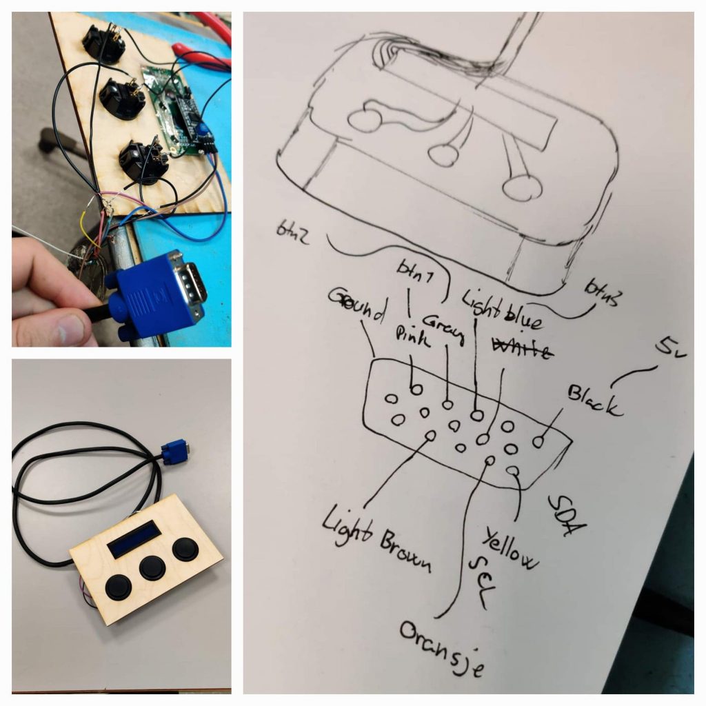
The Controller Unit (CU) originally was planned as hardwired onto the unit itself, but after a shift in UX design, we decided it would be more intuitive if it was units you connect to the main unit, which we can use to make check if the units are connected and thus base game logic on the connected units.
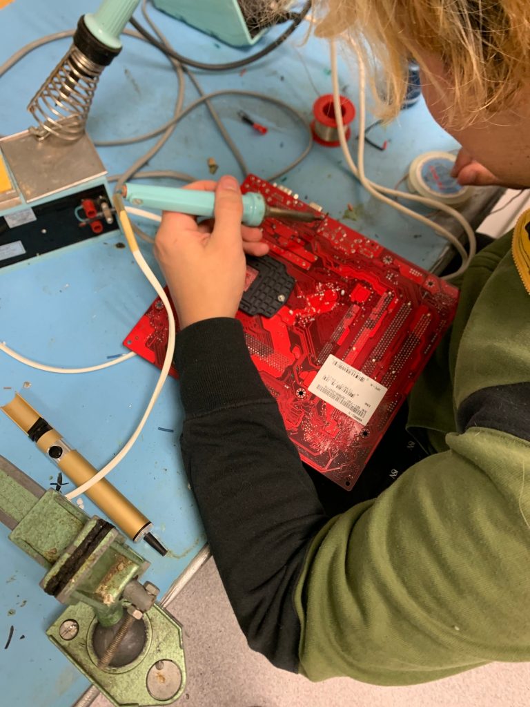
To this end, we had to desolder 4 x VGA inputs, prepare 4 VGA cables, label what data each pin of the cable would transfer, as well as solder the pins on the first prototype of the controller. We plan to label the buttons and change them to a slightly better design.
Work on the image recognition python program, and we now have a python program that finds the contour around the number on the play cards, which we can use to compare to other contours and find the card value. Also worked on the pi and made a python program that takes pictures with the pi camera and saves them to a folder, and those pictures will be used in the image recognition python program.
This post written by Seonhee Kim