Group 1
We started delegating tasks as computer engineers. Each member started working on their own part of the system.
Creating code for grabber
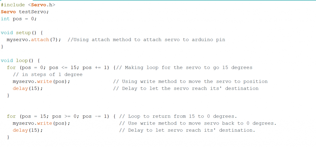
After our mechanical engineers had made their beta claw grabber it was time to create the code for servo motor. To make life easy and check that everything was working I looked up Arduino tutorials for the servo motor. Afterwards I used a simple code to test the servo motor with the grabber mechanism. It went smoothly and it was working. To make life easier for everyone not just for me I used some libraries to avoid many unthinkable errors. Here is a snippet of the code.
Servo.h
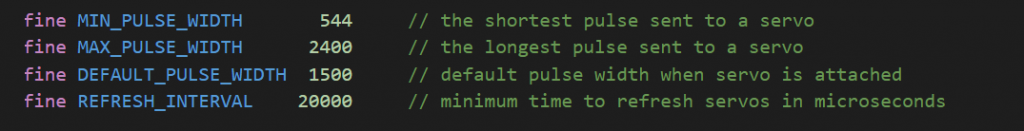
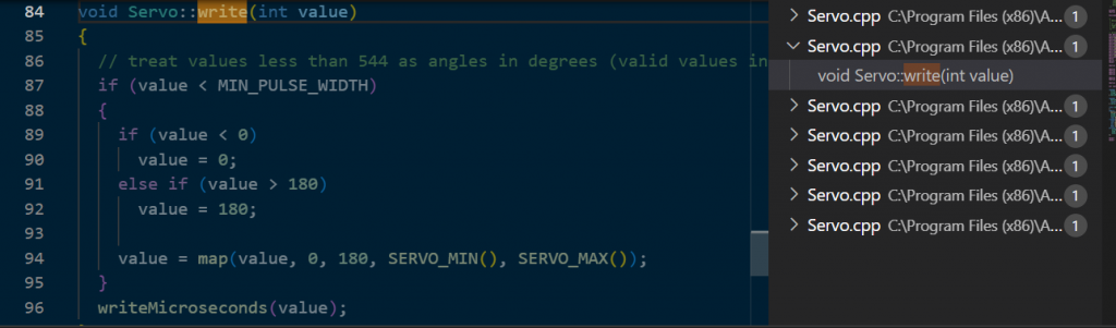
After some research of the servo datasheet and the Servo.h library. I noticed that the library that is used in the code is controlling the servo with how much voltage that is being sent to the servo at a fixed period of 50hz. So if the input value in write function is bigger or same as 544 then it is seen as pulse width in microseconds. Furthermore the max pulse width is according to the library 2400, min pulse width 544, default pulse width is 1500. Otherwise it is seen as angle. Another thing to mention is that if the input value is between 180 and 544 then it is overwritten to 180. If it is between minus value then it is seen as 0. Look figure 5. One could also controll the pulse width width with input values within that threshold but then one has to use the second attach function.


Servo Datasheet
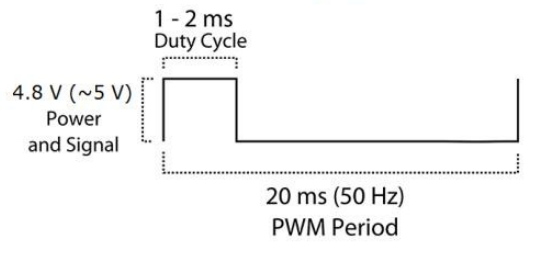
After reading the servo datasheet I could confirm that the library had correct number on the period. In the servo.h library “REFRESH_INTERVAL” is the period and from the picture one can see that the value is 20000 microseconds and that the it has used correct value according to the datasheet. Look below on the picture. Furthermore one has to take into consideration that the arduino needs to give arround 4,8 and 5 voltage for the figur below to be correct. In our case we checked with multimeter and it was giving correct voltage values therefore it works fine. Another thing to mention is the formulas that have been used. The pwm max value 2400/20ms=Shows the pwm value one has to have in order to get 1 ms pulse width. 2400 gives maximum duty cycle.

Git problems
We had some problems with a git push that created some problem. We still do not have that much experience with git and since the computer engeneer that knows the most about git could not be there that day, we struggeled quite a lot. We where very annoyd that it did not work as it should and it messed up our vs Code quite a bit. i got mine working with help quite quick but our problem with git would not be resolved before our git expert could look at the problem. It was quite a easy fix but becuse of this incident we need to learn even more about git and how we use it safe. We also think this is the reason samuel had a two days with mostly troubleshooting as he wrote in the next paragraph.
Engineering life
This week’s work really taught me a lot about being an engineer. It was a rough week since I faced a lot of problems that were not easy to fix. One of them being “OneDrive”, this program made a lot of problems when I wanted to include libraries it made my program crash all time. Now when that is said many would think that it should be an easy problem and not hard to fix. Trust me it is not, it took many hours and man google searches to find out what was causing problems and what I should do. Problem was that everything in my computer was being backed up on one drive. Therefore a lot of data from other subjects would be gone if I took away one drive. One the other hand if I did not take it away the libraries would be included double up. So I thought maybe instead of letting VS code auto generate configuration files for library paths that I should do it manually. That showed itself to be a big problem as well. Since it auto changed the configuration file. Another problem was that there were no easy fix to this problem since I tried to ask for help from our teacher. It was hard for him as well so he told me to just try. So this was my weeks lesson. Engineers sometimes have to solve problems that have not been solved before and it is normal to have rough days it is a part of being engineer.
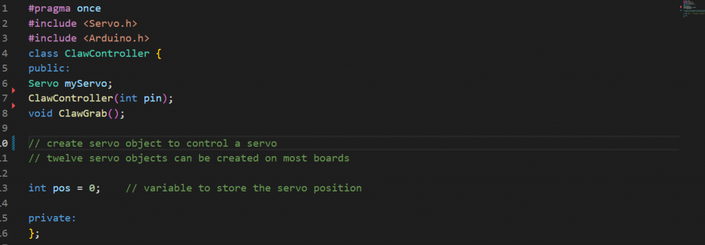
Claw Controller class
The bright side of this weeks work was that I fixed the OneDrive problem in the end after uninstalling many programs and moving all files from one drive and then deleting OneDrive. Then afterwards installing everything back again and now that OneDrive was not there it generated correct configuration file and I was so happy. So now I could finally transform my servo code into object oriented style and merge it together with the projects code. Since the library problems were solved. Here is a snippet of header file. You can also see the video when we tested the code on the claw grabber on the mechanical part. Samuel Said
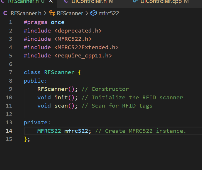
RFScanner controller class
We wanted a way for us to give our system more security in who can use the system. We were thinking that having a RFScanner could be a fun way to unlock the system. I had a RF scanner from our first year, so we used that. I found on arduino how to connect and code it and then i rewrote the code to fit in with our objectoriented programing language. This was a bit difficult but i got it working after a while. So know if we wanted to start the system to give us a item, then you have to scan your card to see if you have permisson to get it.
User Interface System and Button controller
In any system, it is essential to have a user interface. Not only that, it has to be user friendly also. That’s why I decided to make this system simple, and easy to understand. This is the first iteration of our user interface, the “A” phase.
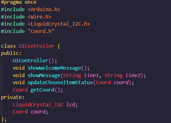
The UI consists of only a few elements. An LCD screen, and three buttons. The screen conveys to the user what the system requires from the user, and information the user will need. Two of the buttons are used for switching between the x and the y coordinates in the linear rail system, and the third button is for submitting a choice.
Here is the header file code for the UIController. It has simple methods for showing messages on the screen, and a few predefined methods for showing welcome messages, choosing item status etc.
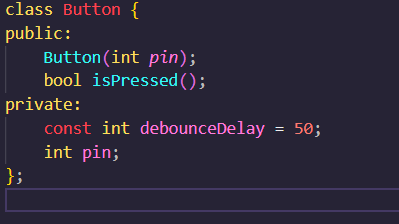
The button class is also very simple. It let’s you define which pin the button object is connected to, and uses a method to check if the button is pressed. The debounce delay defines how long to wait after releasing the button before it registers a new press.
Mechanical
The gripper prototype in a simple design is finished, made it in plywood and lasercutted it. Now computer engineers can program the function to the gripper.
The plywood will be replaced with 3D modelled parts. And some of the gripper will be cowered in plexiglass to see the mechanical function inside. Maby we want to install a couple of diodes to light/blink when the gripper moves.
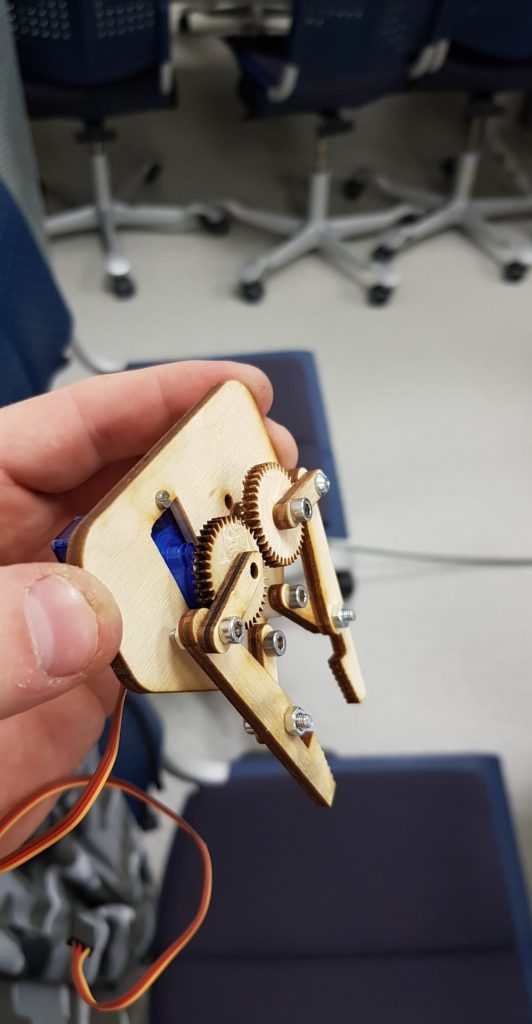
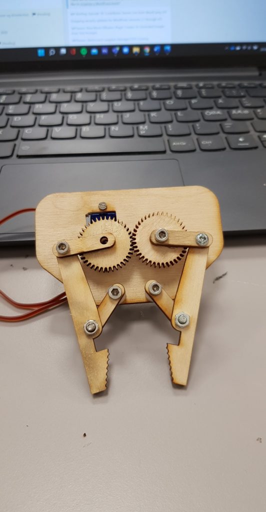
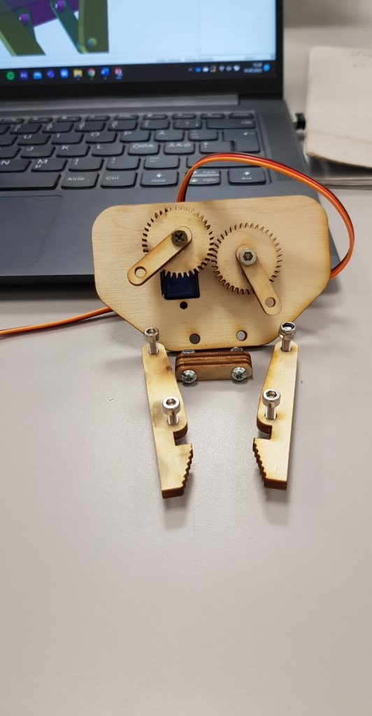
After computer engineers tested the prototype first time.
The parts is not attached enough, this is because i need to modify the gears. They need to be bigger because of exhaustion of the plywood. Its to small teeth on the gear wheel.
- Kim
Redesign
This week we validated our design and our shopping list with counselor Richard. The aluminum extruded rails are too expensive compared to alternative and more reusable options, such as shafts. Taken cost and reusability into further consideration, we decided to redesign the system to use shafts instead of rails. I have begun the redesign of elements so they can fit both the current rails, and the new shafts that we will be ordering, just to keep our options open.
– Ole Markus
Electronics
Still, not much for me to do, so this week I helped assemble the prototype for the gripper and connected its servo motor to the Arduino for testing.
– Mathias