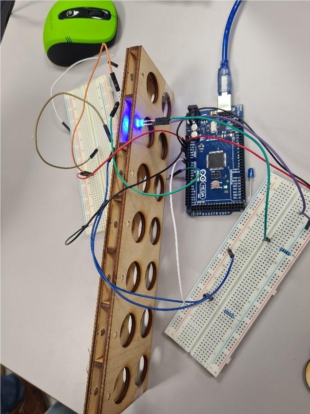
In week 4 we wired electrical connections for the prototype with the photoresistors and blue LEDs for the detection of the coins.
We tested which values we have with and without the LED and came to the decision that we will create the gameboard with LEDs to detect the coins.
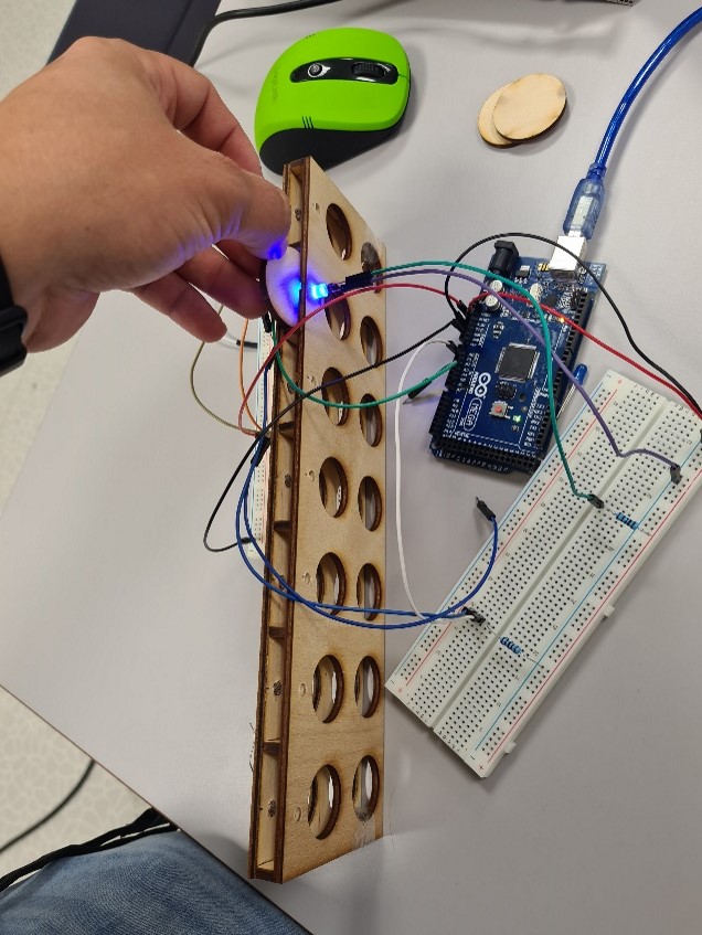
The prototype worked well and we can detect in which row the coin was thrown in.
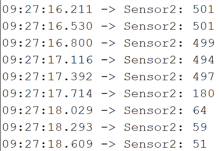
Last four values: The coin was thrown in, it’s dark because of the coins and the values are lower.
For our final game, we want to replace the LEDs with a whole LED stripe (WS2812B 5050). We have to adjust the holes in the wood for it because they have other measurements but we get some good advantages:
- Band is thinner – only a few millimeters, the LEDs stands 0,5cm out of the wood itself and the wires would even be longer (see picture before).
- Band is rgb capable. We can use it for other purposes, for example showing the color of the player.
- Band needs only three connections at the side of it. 5v, ground and signal.
- There are premade libraries for arduino and rasperry pi
The game board has been improved with noses to ensure the parts stay in place. We did some prototyping to check that the design and drawings were good. A few versions were made before the (current) final design was made. The holes for the LED’s and sensors have also been updated to the correct size. To make sure that the computer won’t have an error when the player puts his coin in the hole halfway and then decides to place it in another hole, the board has been made a bit higher so when the coin is halfway into the slot, the sensor won’t register it.