Computer Science
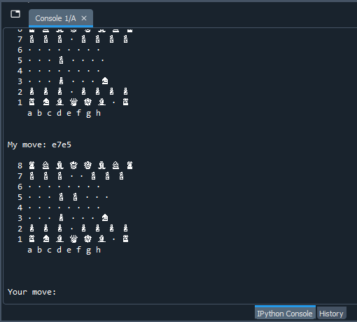
This week we found a chess algorithm we could use which fitted our purpose since it already prints the coordinates for the moves that the machine will be executing. We are currently figuring out how to read and write out these coordinates to a file, which will be transferred to our Arduino board, maybe via Bluetooth, for the robot arm to receive. After testing the program, the algorithm seems to have a high level of skill rating and we didn’t discover any bugs yet. We are also figuring out how we can be able to change the skill rating of the algorithm. To do that we either must change the code and integrate another algorithm from another source, or just use a completely different code.
We also got to test the programming for servo motors and it’s pretty much straight forward. We don’t get to test much more of the servo programming before the robot arm is finished.
We used some time trying to find simulators, but we gave up on that, so for the time being we have put the programming for the arm on hold, instead we used majority of our time this week(7 hours wednesday and 4 hours friday) with the chess algorithm, and researching how to receive and give coordinates through bluetooth or file write/read.
Kevin Johansen, Hossein Sadeghi – Computer Science
Computer Vision
Components and OS
This week I started with a meeting with Zoran to get some components I need to get started. He got me a Raspberry Pi 4 B, a Raspberry Pi touchscreen and a camera module that fits the minicomputer. I did some research on all the components and their requirements regarding the different operating systems size and decided to order a 32 GB micro SD card for the Raspberry Pi.
I haven’t decided on an operating system yet, because I need to choose the method I will use for the computer vision first, as some of them only works on certain OS`s with the Raspberry Pi. I have done a lot of research on using Roboflow for the computer vision part, and it seems to be doable, but it requires UBUNTU as an OS. This will probably be my chosen method but to be sure I’m going to watch a 3-hour beginner course on OpenCV over the weekend and see what I think of it.
Assembling the PI
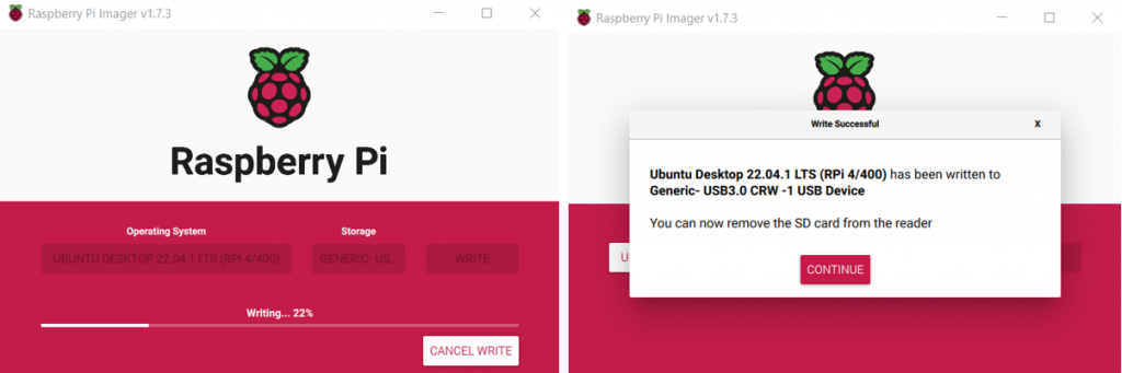
To start collecting data for my dataset I need to assemble the Raspberry Pi and get the camera up and running. I found the OS image that I wanted for now, which was the UBUNTU Desktop for Raspberry Pi 4, and then flashed it onto the micro SD card I had ordered the previous day. This took about 30 minutes and then I got a confirmation saying that the OS had been written to the SD card and I could remove it.
I removed it from my computer and inserted into the SD card slot on the PI. Then I plugged it into my monitor at home, a USB mouse and keyboard and the 5V power supply. I turned it on, but nothing happened.
I started googling for a solution and discovered that the Pi outputs a relatively poor HDMI signal, which means that some devices might not even notice it. So, I decided to try and connect it to the Raspberry Pi touchscreen instead, since it is made for the Pi.
Connecting to the Touchscreen
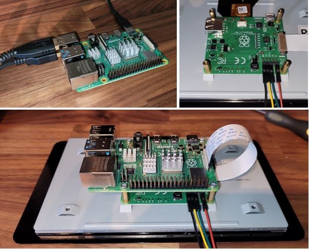
I started connecting the ribbon cable to the DSI pin on the screen, and then connection all the GPIO cables as well. I mounted the Raspberry Pi 4 B on top and connected all the cables from the screen to the matching ports on the Pi.
Connections:
| Touchscreen | Cable | Raspberry Pi 4 B |
| DSI (Display serial interface) | Ribbon cable | DSI Port |
| 5V | Red cable | 5V (GPIO 04) |
| Ground | Black cable | Ground (GPIO 06) |
| SDA (Serial digital interface) | Green cable | GPIO 03 |
| SCL (Clock) | Yellow cable | GPIO 05 |
After assembling all this I put in the power supply again and turned it on, without any luck this time either. Then I started thinking that maybe the SD card didn’t boot correctly or maybe there was something wrong with the OS. I took the card out and installed Raspberry Pi OS (Raspbian) instead, but I was still stuck with a black screen. Next week, I’ll keep working on getting this to function.
Marte Marheim – Computer Science
Mechanical engineering
The Robotic Arm
For week 4 I continued to work on the design, and I have almost completed the whole design and assembly. The motions the arm will go through is somewhat like the motions off a human arm. The parts are designed (with inspiration from google) like “body parts”:
- Base joint
- Shoulder joint
- Elbow joint
- Wrist / hand joint.
The base joint will be run by a stepper motor and will be able to turn 360 degrees. The rest of the joints, except the wrist, will be run by servo motors and will be able to move 180 degrees. The wrist joint will be run by a servomotor with the ability to turn 360 degrees and will be connected to an electromagnet motor.
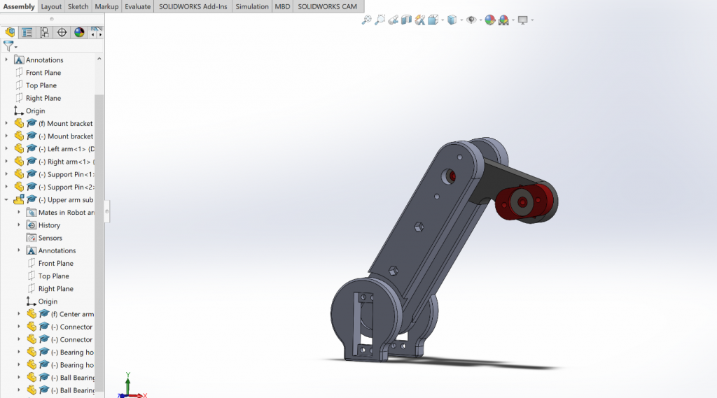
I am close to start printing, but I am currently missing information on the different measurements and dimensions for the servomotor arms. I have designed the arm so that the measurements for the servomotor arms easily can be updated. Once that is finished, and I have made sure that the arm is long enough for it to reach across the whole chess board, I aim to begin with the 3D printing and putting the different parts together.
Chess Pieces
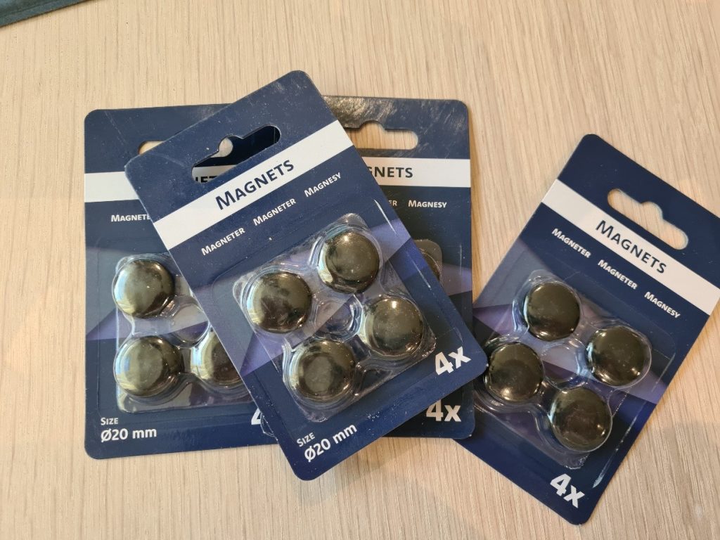
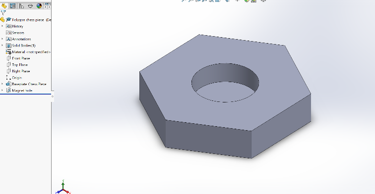
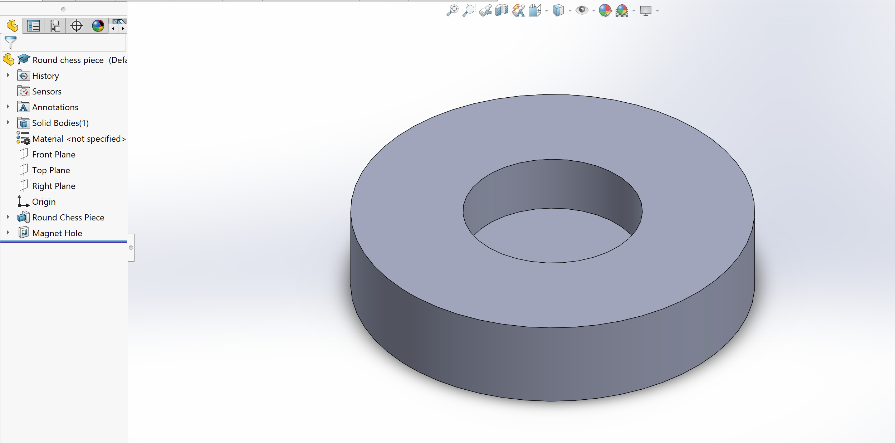
Alongside the design of the arm, I have also started to make the bottom plates for the chess pieces. Earlier this week I went to the store Jula and bought magnets. The magnets will be placed inside the bottom plates, which then will be glued to the chess pieces.
The design of the bottom plates is simple and based on the measurements of the chess pieces. According to the timeline I established for myself, I will be done with the chess pieces after next Wednesday. Given I don`t run into any problems during printing.
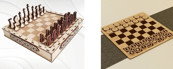
Chess Board
After discussing with the other group members, I have started to prepare the chessboard that I also will be making. Since we will be using a camera to detect the chess pieces and board, we had a discussion on whether we should have a board where the black tiles are engraved on the board or just outlined using simple lines. In conclusion we decided on a board where the tiles will be outlined with simple lines. And if we have time to test and material available, I can make another board where the black tiles are engraved on the board.
Hours spent working on the project, week 4: 19 Hours
Liv Marte Olsen – Mechanical engineering