This week we improved upon the code we already wrote, and finished some of the CNC designs so that they where ready to produce.
Setting up the physical button
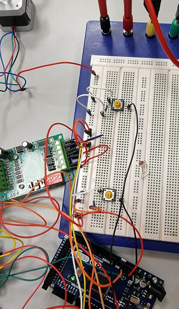
We started working on a way to interact with our system, we where thinking that a button is the first logical interaction we should work on. This button would controll when the motor would go and not. So we wrote first a testcode to check how we would code a button to work. After we have done that we started to test our code. In order to test our code for the button sensors and all the other buttons we had to setup the physical buttons and connect it to arduino. This part showed itself to be more difficult than we thought. For some reason it seemed like the code worked sometimes and sometimes not.
Since in engineering you can never be too sure, we had to troubleshoot the code. So we wanted to see if the button state bool would change at all when we pressed the button. Therefore we implemented some test code. We tried to print out the state with “serial.println”. So this is the weird part since even though we did not press the button the button state went up to high and sometimes to low. We tried to troubleshoot even more by printing out variables that could be the bug. At the time we just could not find the error. So we tried to read the code again and see if there were some logic problem. Still we did not find it. We had a feeling it had to be the buttons. Therefore in the end we had to let the problem slide to next week so that the electrical engineer could be there and since we already had worked over time by several hours we had to end it.
Button troubleshooting
This week our group had gathered together again now we had to try to solve the button problem. We discussed it more with our more experienced computer scientist. He came up with the idea of minimizing the code and cleaning up the main ino file since we had a lot of testing on that file. So therefore we cleaned up the tests and decided that further testing would be on class files. This way it would be easier to troubleshoot. Afterwards he tried to implement his way of code.
Again there were even more problems with the code. So after some troubleshooting it came back up working as it did before but now the same problem that we had last week showed up. After a lot of discussing my colleagues were convinced it was the buttons. Even the electrical engineer were convinced it was the buttons that were not working properly. I was sure that we had missed something so I tried to troubleshoot the code part by part again. Then I found out that one variable acted weird so I talked with the other computer scientist. After some time we found that the programming language could not differ between input variable name that was the same as a variable name that were inside the class. So instead of assigning pin 10 to the variable it assigned -23030. A random number so we hoped that this would fix the problem but it did not.
Seeking help
Now that this problem would not allow itself to be fixed I tried to ask for some ideas from both Zoran and Fahim. Zoran reminded us of a electrical troubleshooting that made us understand what might be the problem. He told us to use multimeter to measure voltage rise when the button is pressed. As planned the multimeter showed 4.9 volt when pressed and 0 when not pressed. On the code on the other hand it showed high even when the button was not pressed and the multimeter showed 0 voltage. Now I thought the problem was the code.
This button code had me really concerned since it had to be fixed before we got more equipment from mechanical engineer. So I shared the problem with a good friend of mine that works with electrical engineer I showed him my code and then how the button was connected. He was suprised aswell that it did not work. After some minutes of talking I came up with an idea that could get us ahead of finding the problem and that was to measure the voltage on the arduino pin since the arduino pin that was giving input could be the problem. This also did not give us a good pitcture of what the problem was.
Taking a step back
After beeing stuck on the button for many hours, we started to feel very lost. we tired very hard to find the error. Some of us was thinking it still was the code and others were thinking it was how the button was set up. We took a good break and went outside to take som air and talk about somthing else than the group work. This helped us a lot, when we came back we removed all the cables that was used for the button and we tried to connect it again. To our suprise it now worked perfectly. We was now sure that it was becuse the button was not connected like it was supposed to be, and we found that a cable was not working. So we learned that we should take more brakes when we are stuck on somthing and take a walk outside to clear our head. After this we connected some more buttons.
User interface
Since we had planned to have a user interface we thought we could look into using our LED screens that we had received from the first year and use that as starting point. This part again required the buttons to work since we thought we would use buttons to assign cordinates at our first beta product and then upgrade it to rasberry pie touch screen.
We did a lot of research on how the LED screen was supposed to work. It was very difficult to get to work becuse the pins that we normaly use for LED screen did not work for some reason, but after a lot of reading we found out what pins we should use and found a libary for the screen. We then wrote a few lines of code to check that it was working.
Code QOL improvements
There has been many improvements to the code we wrote in the previous two weeks, which allows for better readability and quality of life. This means that when we extend upon the codebase it will be easy to do. To be more specific we moved moved a lot of the code from the main INO file into more classes. This way we could make our project more object oriented and future expansion of code would be much easier.
Solving future problems
In order to take care of our linear rail system belt we had find a way for the system to know when it has reached the wall both in x axis and y axis. For this we thought we could use buttons as sensors so that when the x and y hits the button the system knows that it has reached its destination. We also thought that this was a part of a very critical system in our sorting system. Since the machine always have to return to its’ initial position when it starts so that we avoid many bugs in case their have been a power outrage. Therefore this button sensors in x and y had to work properly so that the z claw does not hit the wall and the belt does not get scratched of friction. Furthermore the return to initial position would make the move to position method much easier. Since then we know that it starts from initial position then the math would not be a problem.
CNC Mechanical engineers update
Goals:
- Make a prototype of the gripping mechanism
- The rack and pinion mechanism regulating movement in the y-axis.
- Complete a list of required components
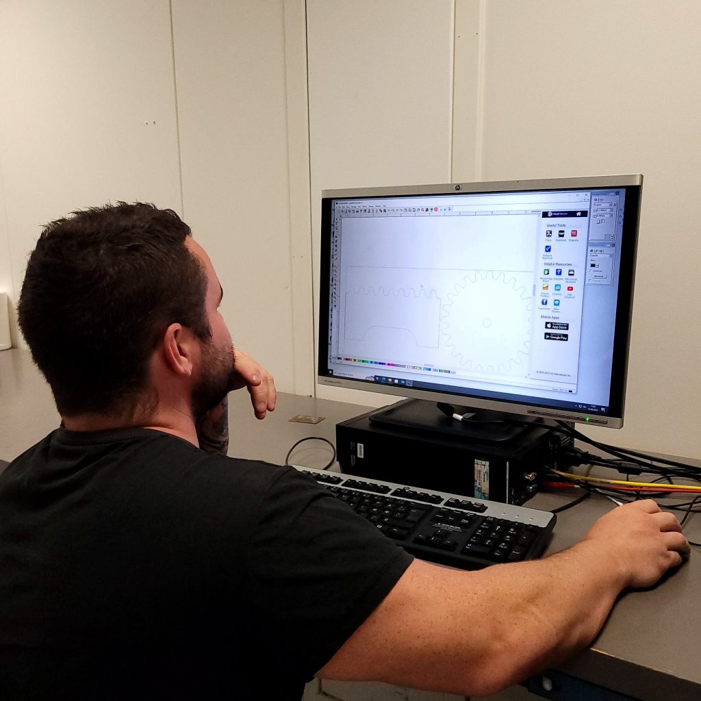
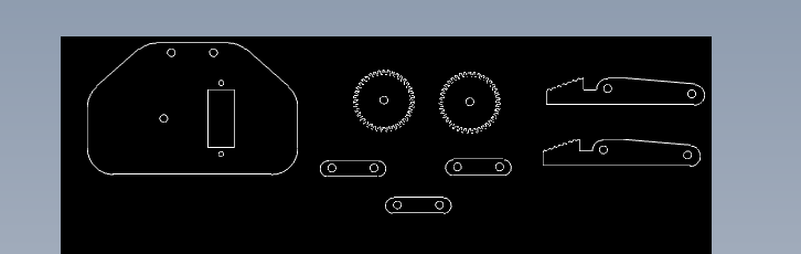
The mechanism regulating movement in the y-axis consists of a rack and pinion. Research on which gear/rack profile was pursued, and based on this research a gear and rack were designed on SolidWorks. We cut out the parts using the lasercutter, and put them together to see if they had a smooth and solid fit. The parts worked well together and are of further use.

A list of mechanical components was finalized after some consultation with counselors:
| Part | Qty. | Note |
| 15mm Linear Guide MGN15 500mm linear rail way + MGN15H Long linear carriage for CNC X Y Z Axis | 3 | Inkluderer både spor og vogn til spor. |
| GT2 Timing belt width 6mm, (2mm pitch) | 1500mm | |
| GT2 Timing Pulley, 20 Teeth, Bore 5mm | 1 | Skal passe med GT2 Timing Belt width 6mm |
| GT2 Idler pulley, 20 Teeth, Bore 5mm | 1 | Skal passe med GT2 Timing Belt width 6mm |
| 2 ball bearings 5x16x5 | 2 | 5 mm indre diameter er viktig |
| Super glue/epoxy | 1 | Skal brukes til å lime metal til metaller eller til treverk/ABS plast |
| Limit switch SS-5GL2 – Mikrobryter SS, 5A, 1CO, 1.47N, Rullearm med hengsel | 3 | Grensebryter |
– Ole Markus Lie
Lasercutting and testing together with Ole Markus. We wanted to see if the plywood could be used as gears and braces.
Continue working with prototype
Today i have worked on the lab with cutting plywood for the gripper/claw prototype. I wanted to get this as soon as possible finished so computer engineers can start to program the grip mechanism.
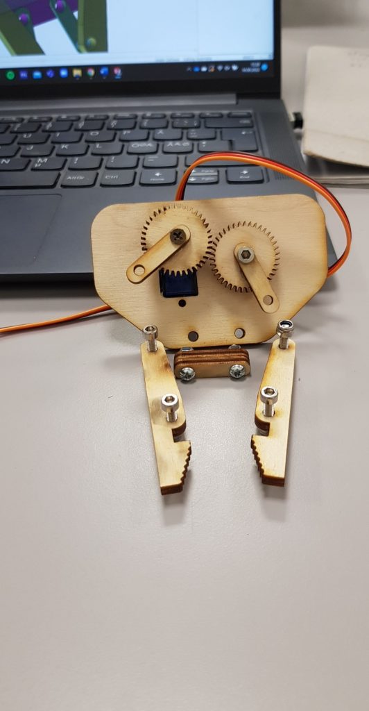
- Kim
Electronics
Currently, there isn’t much for me to do as we are waiting for the machine people to finish printing prototypes and such, so this week I wired up some buttons to the Arduino to test the stepper motors. I also connected an LCD I2C screen for testing to be able to see in real-time what the stepper motors are doing.
– Mathias