This week we changed our name to Sort.It. Now that we had set up one of the motors correctly, we had to connect the wires on the two other motors and doubling up the code for the two other motors. Since we already done it once it was a piece of cake to do it on the two other motors. This video shows a demo of our motor technology.
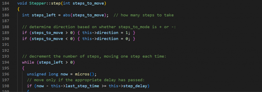
Stepper motor methods
Looking further into the implementation of the library Stepper.h we got more knowledge on how to use the different methods like step() and so on. In the cpp file one could see that negative steps and positive steps were controlling which side the stepper motor should rotate. Another thing to notice is that the method also takes into consideration how much delay the stepper needs to rotate to desired angle. We think that this library could be good for our application.
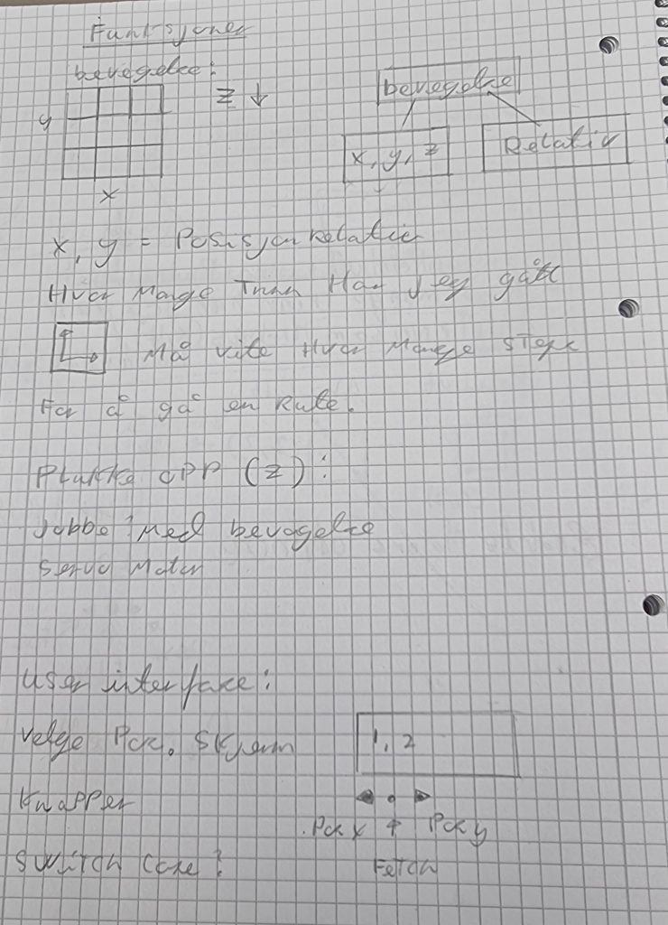
Linear rail system structure
Two of the motors will be used for a linear rail system, which will operate on the x, y axis. The last motor will be used for operating the y axis in our grabbing system which retrieves to components in our sorting system. We had a lot of discussion for how we wanted the motors where supposed to communicate with our system. we talked about using cordinates, but right now we count how many steps its needed to move in the rail system. This way we don’t need to know the exact cordinates just the relative position.
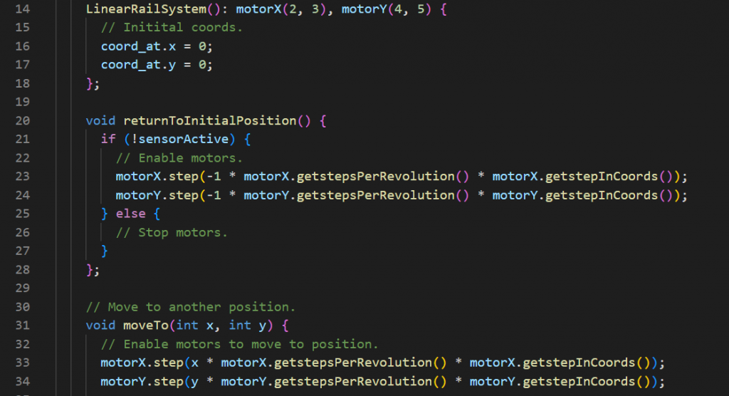
Structuring code and using libraries
In order to make life easier for our self we decided to start structuring the code and make it object oriented and started using libraries. Now it was easier for us to see how our linear rail system would look like in real life. We still coded together but after working hours me and Martin decided to look even deeper into code and structuring the functions more security featured and structured by privatizing variables within classes. We have a screenshot of some parts of the code.
Considering we are using three motors, there is an issue with concurrency in the c++ library we are currently using for the motors, “Servo.h”. It does not support concurrency, meaning only one motor can be active at any given point in time. The solution to this would be to write, or use a library that does not have this limitation.
An exercise in pair programming
This being from the computer engineers perspective. Thus far in our project development we have mostly worked on a single computer when programming for the Arduino microcontroller. The reasons for which are outlined here, in no particular order:
- Because of us being so early in the development cycle, it is important that we use our expertise to focus on one problem at a time.
- Because of technical limitations.
- There is a certain type of programming style referred to as pair programming, which allows us to discuss the quality of the code, and the best solutions. It also allows us to learn from each other.
Upgrading our IDE (Integrated Development Environment)
When we first started developing the software systems for our project, we hit upon some technical limitation with the IDE we were using, the Arduino IDE. It is a very simple program, with very few features. We decided to switch to VS Code which has an Arduino plugin. Two of our programmers have not used VS Code before, so we had to use some time for troubleshooting and learning. we agreed that we would take time outside of the allotted groupetime and learn VS code so we are are not using much of the grouptime. We still have a lot to learn but we work good togheter and we help each other.
Presenting our work
This week we were also tasked with presenting our work so far to the other groups and the lecturers. We had prepared a PowerPoint presentation in advance which outlined our idea, our problem domain, solutions to the problems, and what each member of our group had contributed. We where happy with the outcome of this presentation. We received some questions, and showed a little demo of our technology to the other groups.
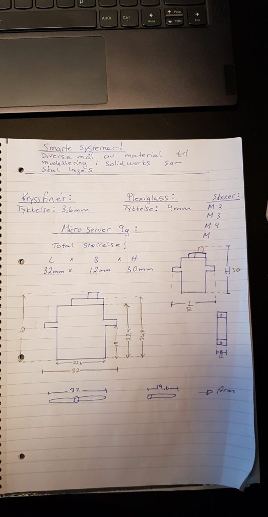
Mechanical
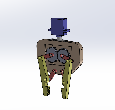
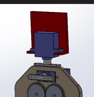
i`m still working with the gripper function/mechanism. Maybe gears and a micro 9g servo motor can do the job/mechanics instead of arms.
We want to have a good grip function aswell, so that the gripper can turn around in 180 dregrees together with grab function.
In the prototype we have 2 micro 9g servo motors. Modelled in SW.
- Kim
Movement in the z-axis
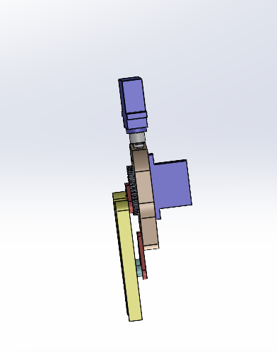
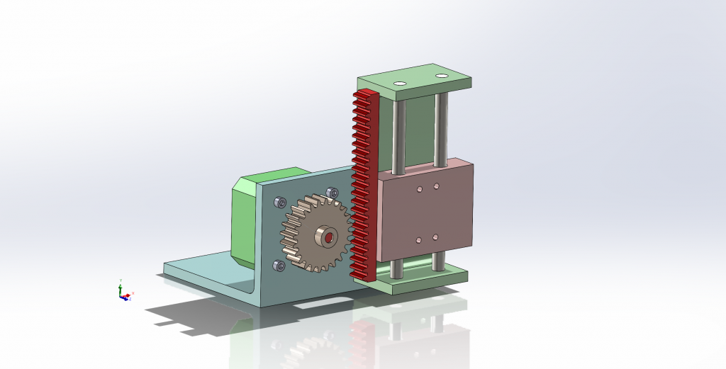
As of yet we’ve discussed multiple mechanical options regarding how the gripper-function should be lowered and lifted on the z-axis. After much deliberation between different mechanisms we approached the solution seen below. The model only demonstates the idea of the mechanism, as it is not yet confirmed or finalized.
– Ole Markus
Just a modified gripper attachment for the z-axis.
To could attach the gripper we need something that could holde the micro server motor together beeing attached with the z-axis attachment that Ole made.
- Kim
Electronics
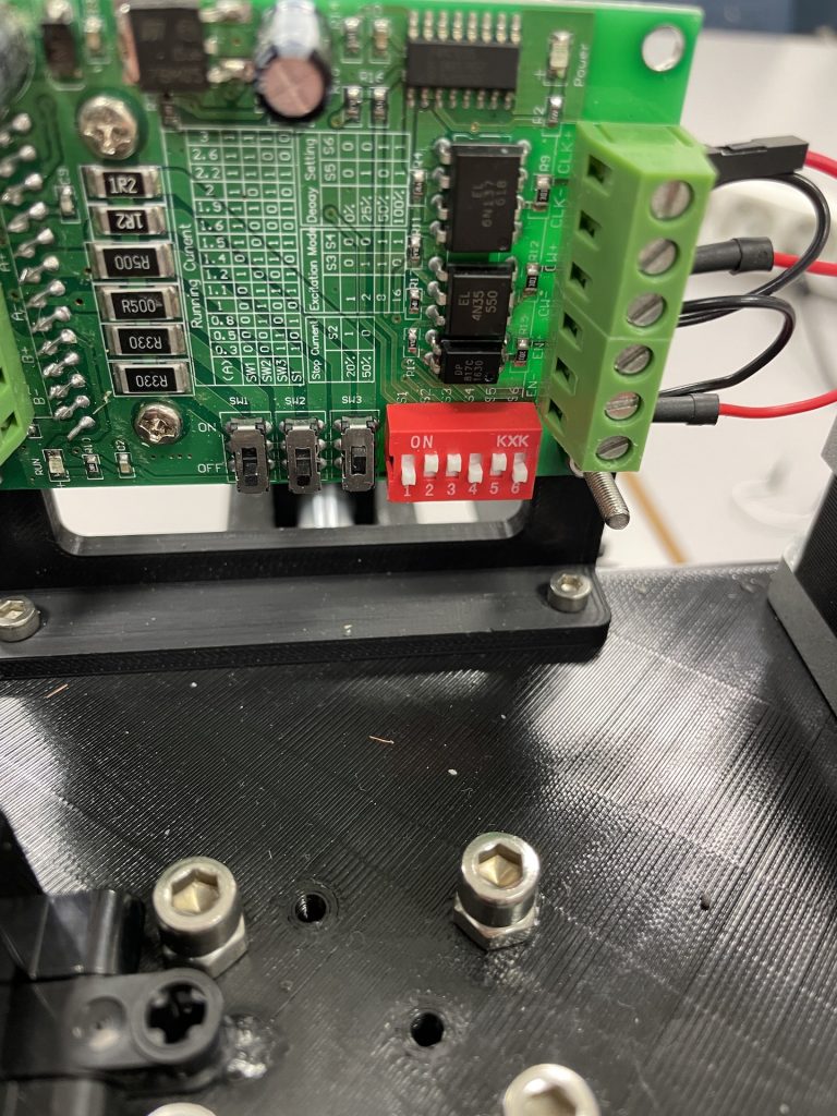
On Wednesdays, I have a lecture on another subject. Therefore, I am not able to meet with the group on Wednesdays. While I was away last Wednesday, the group acquired stepper motors and stepper motor drivers from the teachers. The stepper motor drivers they gave us was the TB6560, which was what they had. This works in our favor for us because we won’t need to add a capacitor to the circuits, and they are very easy to tune regarding the running current. For the rest of the components, we are using parts of the Arduino kit we bought during our first semester at USN.
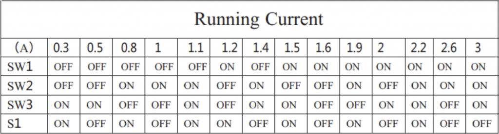
The Nema 17 Stepper Motors are bipolar, which means there are two pole pairs that each makes the motor spin in one direction. Therefore, the motor has four wires to connect to the driver. To find which cable to connect where there is a test you can do in case your specific motor is not wired correctly or you have found the wrong data sheet for example. The test is as simple as pairing two wires and rotating the axle, and when you get resistance, you have found a pair. Then the other two wires are another pair, and you connect them accordingly to the drivers. For all our motors the black and green was one pair, and the red and blue was another, which was the same as in the data sheet. When it came to the running current, which was 0.4A, I did not have to calculate it, as it was written on the side of the motors. I then tuned the drivers accordingly using this table:
However, while connecting everything, two of the switches on two drivers fell off, so I had to take two from one of the extra drivers we got and place them on the drivers we used, because if I did not the motors heated up.
When all the stepper motors and drivers were connected to the Arduino, the computer engineers made a simple code just to test if everything worked properly, which it did.
This is where I went for help with tuning the drivers:
– Mathias