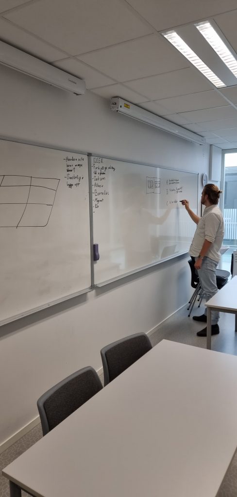
Now that we had figured out that we would have a sorting system. We had to dive deeper into the specifics. We had to investigate what kind of grabbing tool did we needed for our problem. What kind of grabbing tool could be versatile. There were few problems with our ideas about making it “easier” at the beginning stage. Since we thought we could use magnetic puller our we thought our problem would be easier. After investigating more we found out that there were a lot of stuff that could go wrong with that idea. Cause magnets does get weaker over time. Moreover it was hard to figure out how the magnet would pull only one screw at the time. Furthermore, the magnetic idea was not versatile. Therefore, we went on with a claw grabber with four points to grab with for our z direction. It is still not for sure it will be that way but for now it is the claw idea that gives us the most confidence. The reason for claw grabber choice is that all of our engineers do agree that it seems like a good starting point that we could iterate upon and use it for even more fancy sorting system. Here is a shot of our mechanical engineer showing the rest of us some of his ideas.
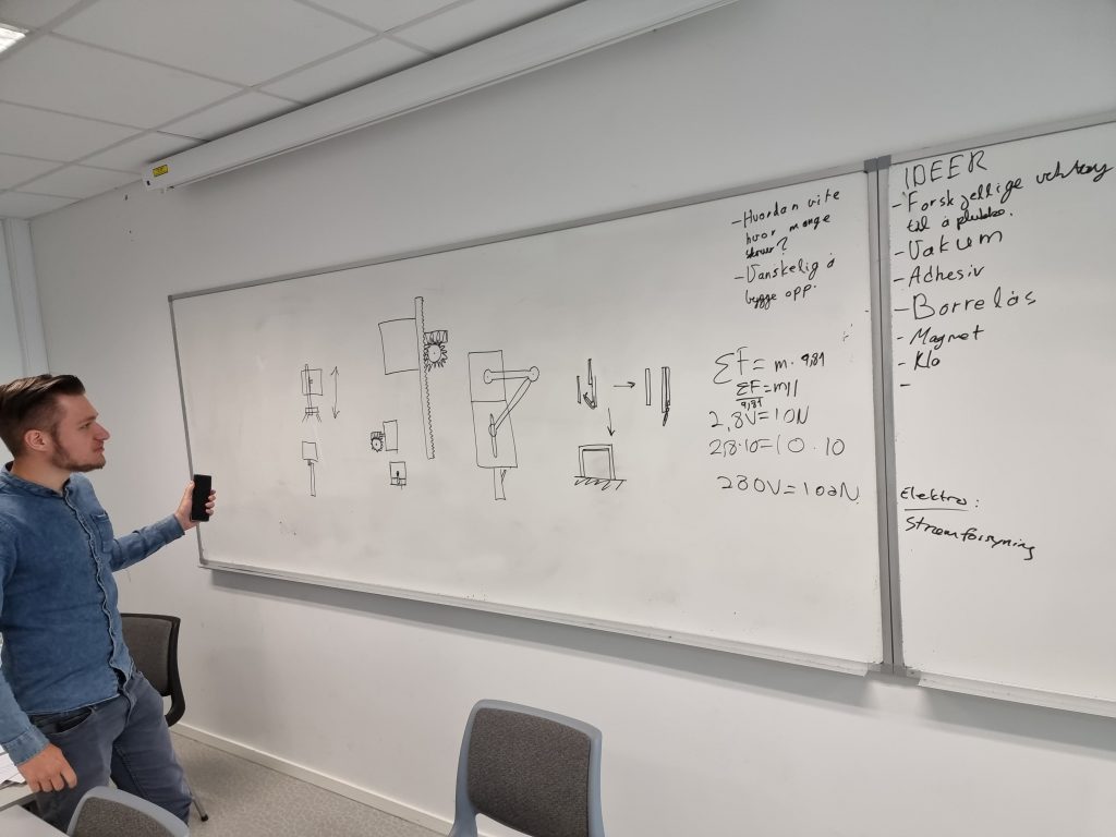
Discussing components needed for the project
This part was crucial and very important for our progress. To keep up our group’s velocity we had to be productive and effective on our product so that we could be one of the first groups to gather crucial components we needed for our project. Luckily, we had foreseen our task from many perspectives, and we were sure about which components we needed. Some would wonder how we made it and the answer would be that each engineer field in our group had to think about the most vital components they needed. That way we knew exactly what we needed to start with. Here is the list for components we thought about for this particular week.
3x MGN15H Linear rail
2x GT2 Pulley r2 w/ 20 teeth w/ bore diameter = 5 mm
1x GT2 Idler Pulley r1
5m X GT2 Timing belt
2x Nema17 motor(48mm depth)
1x Nema17 motor(23mm depth)
4x kabel til nema17 motor
4x A4988 Driver for nema17
12V PSU
5V PSU
Epoxy til metall
1x Arduino
(1x Raspberry PI) – låne
1x Batteri til arduino
små komponenter til arduino – kabler etc.
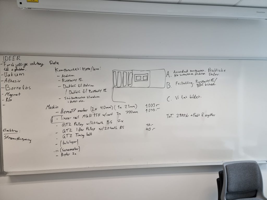
Discussing new ABC requirements
Just with every project there have to be done alterations in the requirements as the project progresses. Therefore, after many some iterations we had to alter some of our requirements. The good part was that we already had some alternatives ready so that the group could directly start discussing. Our arguments had to be referenced from the task’s requirements. Therefore we used the tasks requirements as a reference point and altered our requirements. We knew that we had to have some interaction with the environment and the user. Here is ABC requirement for now.
| A | B | C |
| -Sorteringssystem -Hente komponenter (Begynne enkelt og legge på komplikasjoner) -Registrere lån av komponenter -Graphical user interface for søk og lån – arduino – Skal være skalerbart | -Levere komponenter fra bruker til designert plass -Registrere og legge til nye komponenter -Identifisere at det er riktige komponenter som er levert – raspberryPI/BBC microbit | -Hente mer komplekse komponenter som elektriske komponenter |
Planning and starting to code
We started our day with a lot of planning, we were ready to finally do some coding. Previously on the planning phase we had emphasized that we were going to use one drive in combination with Git and Github as repository. Since one of our group members had used git before that was a good chance for the rest of us to learn. So our group member showed us how we could use git before we went on to do some coding. To start with it was hard for us to make particular programming sections for every individual software engineers. Therefore, we had to do some triple programming together. We where thinking that coding toghter in the start would be better for us later. This way we all have a say in how the foundation of our system is made and how it looks. We want to code in a way that is easy to understand. We write our code in visual studio code and arduno.
Gathering the motors
We needed motors for our system so our mechanical engeers looked at a few different motors and after a bit they chose the one we are using now. We had an idea of how the motors would work in the linear rail system since we had a lot of planning with the mechanical engineers and some planning with the electrical engineer. We were still not sure how much the motors had to be on to reach a certain box in x and y direction. Therefore we just went about creating the variables and variable types for the future. We also wanted to use the modern programming techniques we were taught earlier in the course. So we had this idea that we were going to have object oriented programming design. That was not our first particular goal at the beginning. Since the most important goal for the beginning was that we made the motor turn on. That in itself showed itself to be difficult since at the day our electrical engineer had another subject and we needed to connect the motor to a driver in order to be able to run any code. We had to be effective and could not wait for the day we had planned to meet with the electrical engineer. So therefore, we looked up the internet on how to connect the wires between driver, motor and Arduino.
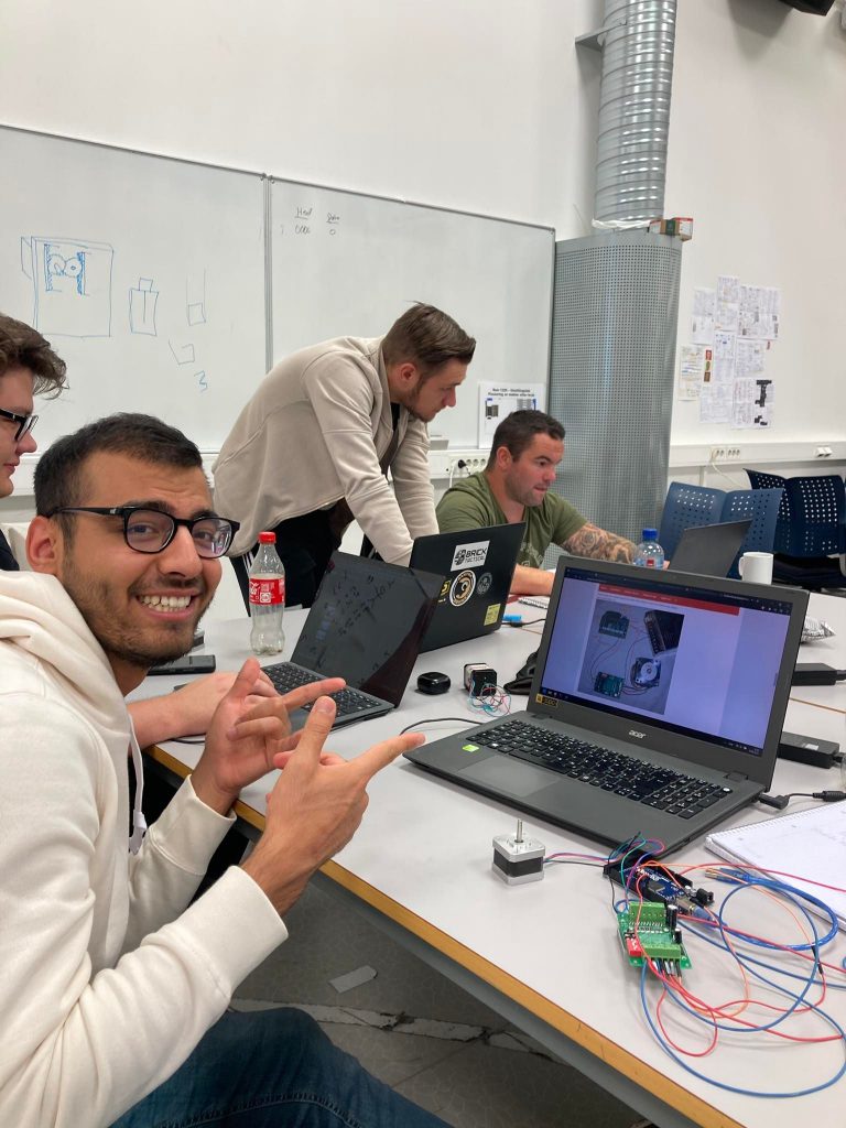
Troubleshooting
After connecting up the driver with the motor we were a bit afraid of ruining the motor. So we investigated a lot on the internet and asked the teacher if we could connect it to power and test. Since we had looked up on many sites we were told that we could go ahead and live on the edge. We went ahead but the motor did not turn on when we ran the code. Therefore we had to isolate the problem. We went on by troubleshooting the code first and checking with several other websites. Then we came by a code that was relative simple so we used it to test and it worked so we did not need to go ahead on troubleshooting the wires. We were pretty sure that the problem was the code since the drivers were on and the Arduino were on. Here is happy face after making it.
Mechanical design
The mechanical design of the system in development is based upon the functions it must carry out. An item must be retrieved from or released to a sector of a 3×3 grid and thereafter moved to a specified location within a 2D plane. At minimum, this requires movement in the x, y and z axis. The z axis is relevant because a function must be lowered and raised to pick up or put down items. In addition the system must be scalable. We concluded that a linear rail system would be the most viable option, based on these functions and requirements.
Linear Rail system
Research of previous linear rail systems both online and physically at campus resulted in many different options and possibilties for how components should interact with each other. The Plotter from How to Mechatronics proved very helpful during the design of the initial 3D model on Solid Works, as well as providing possible options regarding available components.
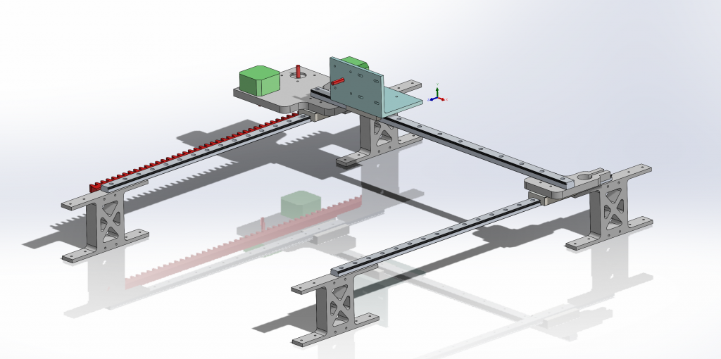
The rails in the system have their respective railcarts with ball bearings, as to ensure ease of movement. These rails must be purchased. We concluded that the Central platform on the x-axis can be moved by 1 nema 17 stepper motor with a belt connected to the stepper motor, the central platform and an idle pulley on the left platform.
Y-axis issues
Ideally, the movement on the y-axis should be scalable. As our prototype should reflect this, some issues arose as to which solution should be chosen. The method of production must also be considered, which causes further complications. We decided a rubber belt would not be viable over long distances due to creeping in a long rubber belt over time, and difficulty during assembly on a large scale. We therefore wanted to use a rack and pinion mechanism, as this is the most scalable. A rack and pinion can have two different configurations; a circular rod with machine threads, or a rectangular bar with teeth. Over large distances, for instance in a warehouse, the circular rod could have issues maintaining its level in the horizontal dimensjon. A rectangular bar with teeth (rack) could however be mounted in sections, presuming high precision during installation.
Production
Initially, production would be limited to 3D printing. This would prove a problem as our system requires elements such as the rack. The rack must be 500 mm long, while the 3D printer can print elements in a 280×280 mm cube. This caused some discussion as to which solution was most viable, both scalability and production taken into consideration. However, after further consultation with counselor Richard Thue, we realized plywood could be used for the larger elements. This shifted our perspective to create more components in plywood with a lasercutter, as this production method can be more beneficial for prototyping komponents while keep time and costs on the minimum.
– Ole Markus
Cooperation together with Ole Markus
The second week we decided to go for a rail system. I have had some experience with this before so after discussing with Ole we started right away to make a prototype/modell. Ole did the 3D modell of the rail system and i tried to make a claw/gripper for the rail system.
This was a try and fail because of the mechanics must work properly.
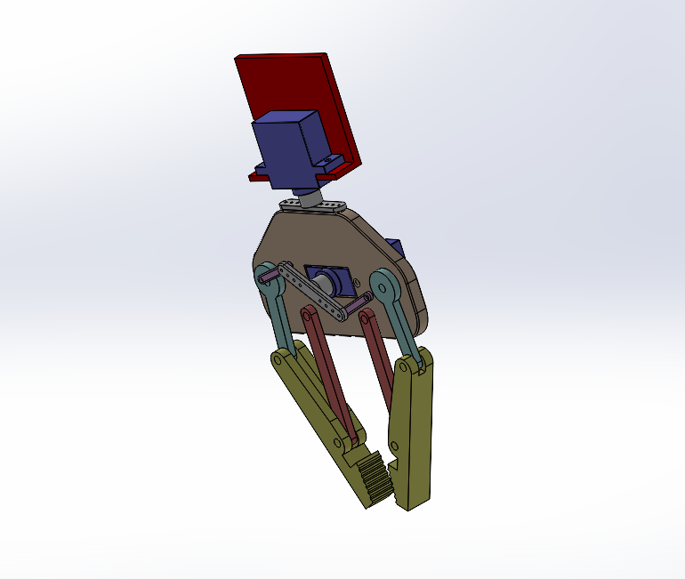
First gripper prototype. We wanted a simple mechanics that could work. This is not the gripper that is going to be in the rail system but just to se if we could get the gripper to function in Solidworks.
-Kim
Electronics
This week I did some research on what drivers and power supply and such we need for the stepper motors. The reason we are using stepper motors is that they can move to a known interval and hold that position. They are also very good for moving objects to repeatable positions and are often used in 3D printers, which our system resembles a lot. After searching the web for a while I found out that for the Nema 17 Stepper Motors, a good choice for drivers is the A4988 Stepper Motor Drivers. However, for it to work with the stepper motor I need to add a capacitor of 100µF to the circuit. I will also need some cooling ribs for the drivers. We will also need a 12V power supply and some Nema 17 Stepper Motor cables if they are not already included with the stepper motor.
I will also have to find out how much current the stepper motors use so I can tune the drivers to make sure they do not push too much current because then the stepper motors will heat up. This can be done either by finding the stepper motor’s Vref and multiplying it by 2.5 to find the current limit, or I can look at the specifications for the stepper motor, where it should be specified.
We will also be using an Arduino Mega 2560 to communicate the stepper motors and all the components we will be adding soon.
– Mathias