Gaute
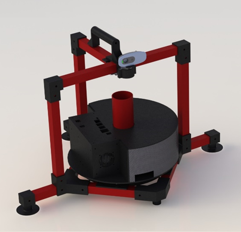
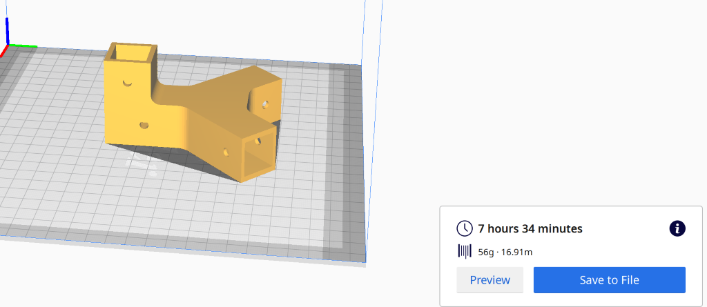
This is the final design that we landed on.
There has been a lot of work put down in the process to get where we are now.
A tremendous amount of hours in solidworks and many iterations on each part pays of when it comes to the end product.
I have based the design of the part so that they either can’t be 3D-printed or cut out of plywood on the laser cutter. All the hole dimensions that is decided by me is either 3mm or 5mm, making the assembly easier with lesser dimensions to keep track on. The filament for the 3D-printed part are generic PLA bought on Clas Ohlson, and the plywood is standard 3.5mm thickness.
I have not built up all the parts in the easies and most-forward way, that is simply because I didn’t know how the part was going to turn out before I started designing. There are some pros and cons by doing it that way, the cons are the feature tree is ugly as hell and doesn’t make much sense as you go down, the pros is that you are able to see how I built the part all the way from the first extrude till the last cut. There is no problem for me to make a new clean part and use the dimensions from the “ugly” part so that the feature tree is nice and tidy, but that doesn’t tell the whole truth about how much work is put into making a nice and functional part.
Halvard
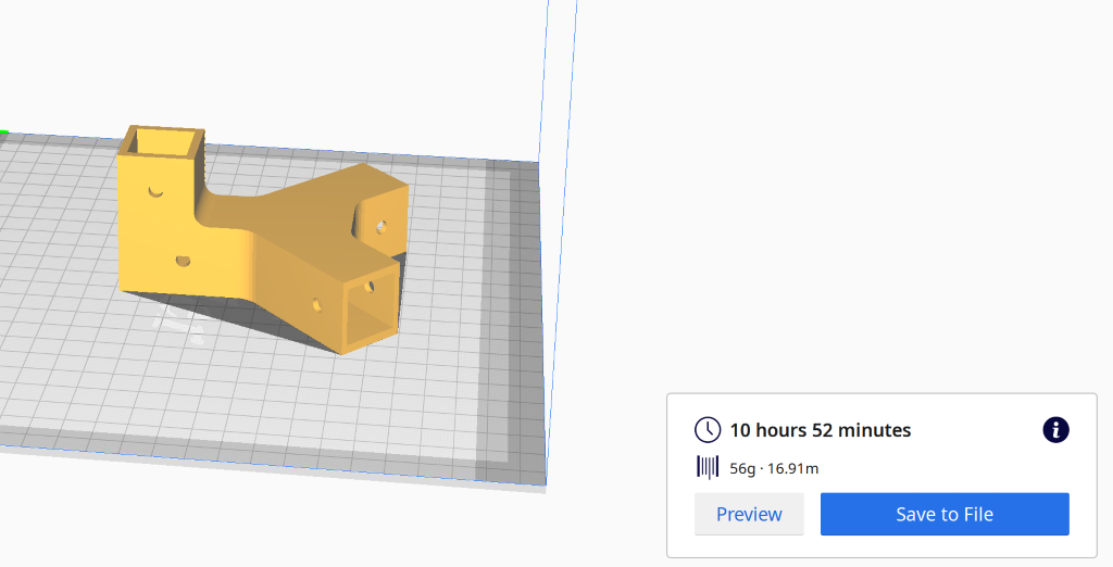
This week we have been finalizing the project, for my part that has been to design and print parts, assemble the machine and fixing problems that we encountered. The first part of the week Gaute and I spent sourcing and assembling parts for the machine. The parts that are 3d-printed are mostly printed inn PLA. The reason for this is that PLA can be printed fast and easy, which makes it great for fast prototyping. Regular PLA is usually a little brittle and not considered to be great for outdoor use, but we found a special type of PLA, the PRIMASELECT PLA PRO filament. https://primacreator.com/collections/pla-pro/products/primaselect%E2%84%A2-pla-pro?variant=61748371979
The filament we choose for parts that need strength is engineered for demanding industrial applications. We shortened down the print time significantly since we were able to print as fast as 120mm/s, however we only printed at 75-80mm/s. The material also has a very high heat resistance up to 95°C+ after an annealing process. It also has excellent mechanical properties (check figure 1 for info)
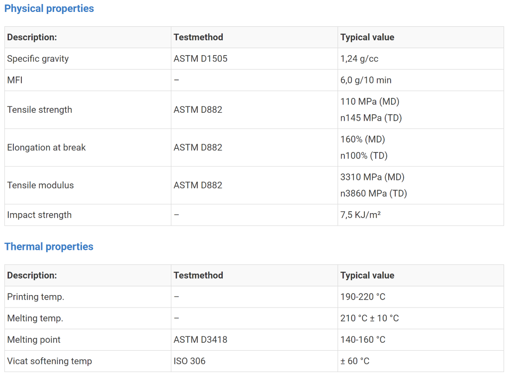
We also choose to only use black filament since the coloring they use helps with UV protection. It also has a matte surface finish that helps concealing the printed layers for a better surface look.
The heat treatment the material will go through after it has been printed will be to make sure that we are fusing the layers together, but for some materials this will be an annealing process. In the case of PLA which is a semi-crystalline polyester thermoplastic it will shift from a mostly amorph to a crystalline product, this will give us more strength and durability. However, there are some disadvantages to this method. The PLA will slightly change form during this process, therefore I have printed 10mmX10mmX10mm cubes so we can map out the deformation in X, Y and Z- direction. In the generic PLA the shrink was approximately 5%, this means that a part that is 10mm will have a deviation of 0.5mm. This would not be a problem If the shrinkage were uniform in the X, Y and Z axis, but it is not therefore you cannot just upscale the part.
The PRIMASELECT PLA PRO filament we used for some of the parts have been specially designed to be annealed which means that the shrinkage problem has been almost solved, it has a stated shrinkage of about 0.27% for an annealing process in the oven at 110°C for 30 minutes and letting the part cool with the oven. In our test it had a shrinkage of 0.34% this means that for a part that is 10mm the shrink will be less than 0.04mm this means that it has less margin for error than the 3d-printer.
The PRIMASELECT PLA PRO was printed at 225°C with a heated glass bed at 50°C.
The generic PLA that we used was printed for parts that were not going to be subjected to large forces and it was printed at 200°C
Anders
Finally done with all other subjects this semester and ready to put in a final effort in our Smart System project. The past couple of weeks have been quiet regarding this project mainly because there where nothing needed to be done with the software for the project, other than tuning the software once the hardware was ready.
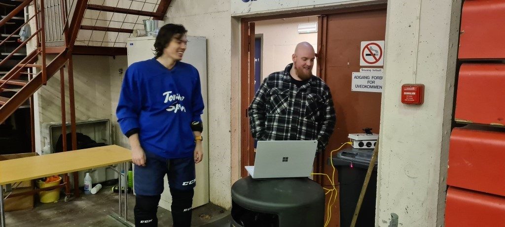
Monday, we went to the ice rink in Kongsberg to do some tracking testing with the test box we made earlier this semester. The tracking seemed to work as intended but we encountered some issues as we had implemented a different stepper motor on the actual machine and there no longer was any support for the test setup stepper in our code. Seeing how the tracking worked close to perfectly even in the weird lighting conditions inside of Kongsberghallen, we decided that we were satisfied for the day.
Thursday, I had to work so I couldn’t find the time to attend the group meeting, but from what I hear there is just the printing of the final parts left before we can start to assemble the machine and finalizing the product.
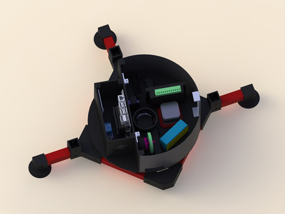
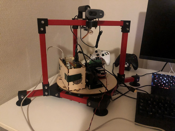
Wednesday this week all the hardware components where done and I started soldering on the electrical components to the physical machine. During this procedure we found there was made some changes to the physical model not reflected in the wiring schematics, Nicholas quickly updated the schematics and color coded some of the wiring in the diagram for ease of use. Once we had the wiring figured out and every part connected, we got into getting the stepper moving the plate in accordance with the data sent from the image recognition software. As it turns out the stepper did not work correctly when sent values in whole steps but works properly when values in half steps where sent. Having the turning mechanism figured out properly late into the night we called it a day.
Thursday, we wired on the Electronic Speed Controller (ESC) for the servo motor and encounter another problem when running our calibrating sequence. This new ESC had some issues using the same delay intervals as the previously used ESC but seeing how much bigger the original ESC was as it is intended to run four motors on a quad copter we decided to try and figure things out. After some testing and failure, we found a set of intervals which did the trick and ended up using the new smaller ESC.
Status:
The machine is all done and all that is left is securing all screws as the machine is actively trying to tear itself apart when active. Other than that, we will do some final testing at the ice rink tomorrow where we also plan to do more filming and getting everything ready for the presentation of our project next week.
All in all, the project came out better than initially expected and we had good communication and progress across the different engineering disciplines. I think we all can call this a positive learning experience and look forward to presenting you all our project next week. Signing out.
Nicholas
Electrical
As we enter the final week of the project we have lot’s of work left to do. The major work left is mounting all the components, connecting them and then test and verify everything. Starting off I finished the wiring schematic before starting. Electrical schematics can be found here: https://1drv.ms/u/s!AkdxjMLchtDupYs-xqFKX6RtvgZp9Q?e=GpYWCP
Please note that there are some components that are in the wiring diagrams that are not present on the actual model. If we have the time and components we will connect the, if not the system will work fine without it.
Anders helped me by soldering wires onto plugs that fit in the Arduino card so we wouldn’t have any loose wires. One thing I really dislike is to troubleshoot due to faulty connections. With the wires soldered I connected everything and made sure it was working as intended. Currently we are using a USB cable from the Jetson Nano to the Arduino to send both data and power. One improvement that could be made here would be to use the expansion header on the Jetson to wire directly to the TX and RX on the Arduino. However, as the Jetson works on 3V3 logic and the Arduino works on 5V I would need to add a level shifter to protect the Jetson. I would also need to add a separate power source to the Arduino card.
One thing that is not portable at the moment is the Jetson Nano as it needs a power supply of 5V 4A. It might be able to borrow a suitable buck converter from a friend, but if that is not possible we will just have to connect it to an wall outlet.
I also spent some time finetuning the stepper driver. As mentioned earlier, there are dip-switches on the driver which are used to configure both max current as well as micro steps. Originally I had it set to full steps and a current limit of 1A. This proved to be insufficient so I looked up the datasheet for the NEMA 17 stepper and found that the coils were rated for 1.5A. Still, after changing this, the result was not desirable and the stepper seemed to miss some steps. I then decided to change the driver to ½ steps which improved the results immensely and the stepper now operated relatively smoothly.
Software
This week I spent most of my time finetuning the software and integrating it with the finished hardware. As we had tested all the parts separately before mounting them there were no huge surprises and everything went pretty smoothly. I downloaded the newest python scripts for the image processing part and made sure they ran fine there. Fortunately they did and I only had one problem and that was with the file formatting, and more specially the line endings. I wrote the scripts on Windows which uses CR+LF while Linux uses LF. This caused the terminal to throw an error on the first line of the script which calls the Python environment with “#!/usr/bin python3”. Downloading the program dos2unix and converting the files made the problem go away. The rest of the script with the new changes, like headless mode etc. to work without a display attached, worked perfectly. I must admit though that I cheated a bit and manually entered the Arduino com port into the code for the Linux version as the solution for Linux isn’t perfect in its current state. The only thing remaining now is to get the Jetson Nano to start the script on power up. Currently I have to remote into it with SSH to start the script, which works, but is waste of time as it can be done automatically.
One thing I had not been able to test before was the loading mechanism of the pucks. We ended up using a continuous servo for this task. After reading the datasheet I found at that I turns clockwise when given a pulse greater than 1.5ms (up to 2.0ms) and it turns counter clockwise for pulses less than 1.5ms (down to 1.0ms). There was also a small potmeter that was used to calibrate the zero point of the servo. That is, the point where it would not move in either direction. To calibrate it I connected it to an Arduino board with a simple program that continuously wrote 1.5ms pulses to the servo. I then adjusted the potmeter until the servo was not moving anymore. The loading mechanism itself is simple. The loading arm is pulled all the way back, allowing a puck to fall down, before moving forward again and feeding the puck to the firing wheel. As this is a continuous servo it does not give any feedback so I cannot know where it is. Of course, I could create a function based on the datasheet that calculates the total distance moved based on the RPM of the servo as well as the gear. However, I ended up just manually testing how long I should run for and fine tuning the values by hand.
Also planned was an arming signal from the Jetson that would allow the Arduino to shoot. However, I decided to not implement it currently as the code on the computer has no form of safety check that would make the arming signal relevant. Instead I added a timer for the fire rate so it would be some delay between pucks fired.
The last bit was the ESC calibration. As Halvard had brought a new ESC we had to tweak the calibration a bit. Also, the auto mode on the Arduino supports for configuring the motor speed on the fly. However, I ended up just hardcoding the values to assure safe operations for now.
I was relieved to see that the integration process went as well as it did and I’m happy I did a lot of testing earlier in the semester on the different component separately.
All the code is located her: https://github.com/NichoPellic/hockey_passing_machine/
Also, the code used can be found in the dev branch. I have mainly been working on the dev branch lately and I simply haven’t bothered merging the dev branch with the master branch yet.
Final testing
Here are two videos from our final testing. The only thing left now is to tidy up the project and do some proper cable management. The videos can also be found here: https://1drv.ms/u/s!AkdxjMLchtDupYs-xqFKX6RtvgZp9Q?e=GpYWCP