Summary: We went through some drastic changes, made big progress and are very close to completion
#1 Cannon Design Changes, Daniel
#2 Projectile calculations, David
For many weeks now I have worked on the cannon with a flawed way of approach.
The original concept was to make a cannon that could launch different types of projectiles. As long as they fit in the barrel, they would launch.
I, for some reason made up the requirement that cannon needed to be self tensioning. This proposed so many different problems that I wanted to give up. Pulleys, gears,
helical-gears, spurs. well you name it and I probably tried it.
But David, mentioned to me a few days ago that since we are going to load the cannon each time anyway, there is no need for us to complicate matters more than necessary.
So now we are going to tension the cannon ourselves.
You can think of this system as a Trebuchet/potatocannon. In both cases you need to prep the mechanism yourself.
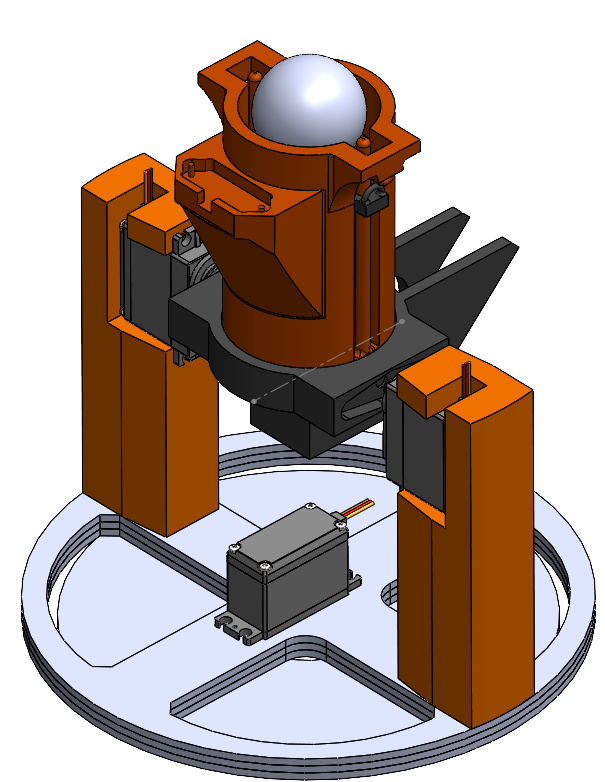
Therefore, a redesign was in order. inn addition to this, as you can see in the picture above. the cannon is “a bit” more sturdy looking that the last model. This is because we decided that the bigger “TOWER-PRO” servo was more suited for the task, as we how components that were heavier.
As you can see, the tension spring mounts are also in place. Though they seem frail, they are actually quite sturdy thanks to some filets and the godsend that is the circular shape.
#2 Projectile calculations
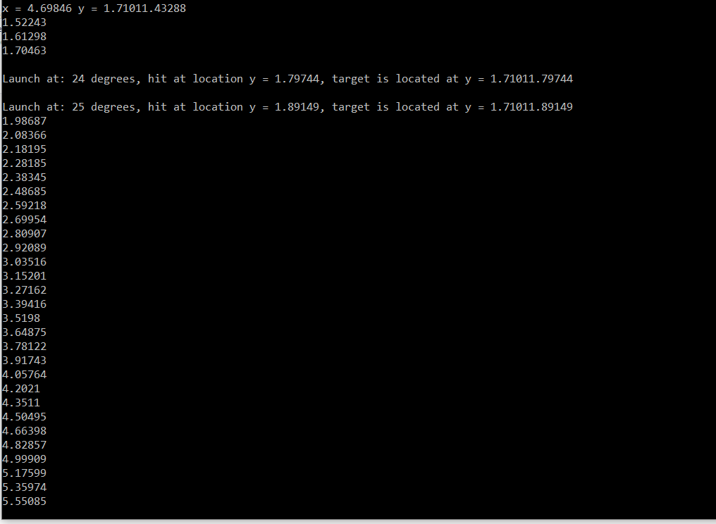
It’s been a lot of work, but the pieces are starting to come together. For a long time now, I have been working to introduce the projectile calculation software to our cannon which role it is to adjust the angle of the cannon in a precise way so that it fires within +-0,2 m of the target.
Using physics calculations and trigonometry we can establish the location of the target and the desired input angel for our servo motor to hit within acceptable error-ranges of the target. The registered target is mapped onto an x and y axis relative the lidar measurement. Those coordinates are then “aimed” at by our projectile class which iterates on different angles (which in turn produces different velocity vectors). Using a parametric equation for x and y axis helps us to figure out what y coordinates are hit at a given time when the projectile crosses the x coordinates of the target. If the y coordinate hit is within 0.2m of the target, it signals a successful launch.
The issue at hand is to figure out the initial velocity and the effects of drag on the projectile, which are hard to do without experimentation. The placeholders for these are put into the software so that it is easily adjustable. The projectile software component also needs to communicate with our servo motor through the arduino ide and the lidar.