After a two week famine, we are cracking back at it.
Working on dialing our Lidar unit, fine tuning of servos, more 3d-modeling and more.
Looking forward to going full throttle again!
Table of contents:
- pulley system
- Stepper motor
- Servo motor
1. continuing of the pulley system:

I am also considering switching to a gear based retraction system for the launch plate.
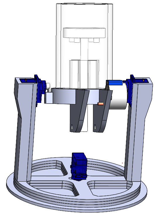
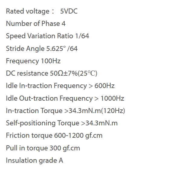
2. Stepper motor
A stepper motor is responsible for turning the ball-bearing which in turn pulls the launch plate downwards. The stepper motor turns in certain increments
and keeps that position. It rotates a specific amount of degrees with a desired speed.
Now the stepper motor functions with our current code, but there is work to be done to calculate the physical work that it does to the springs which power
the launch plate.
The way forward is to figure out just how much work needs to be done to the springs to actualize a given speed to the projectile. Now that comes
from understanding just how much work the stepper motor does by rotating, and then we can use that knowledge to figure out just how much that work speeds up our projectile.
At the arrival of our 3-d printed cannon we can start to look at how the stepper motor also fits onto the design.
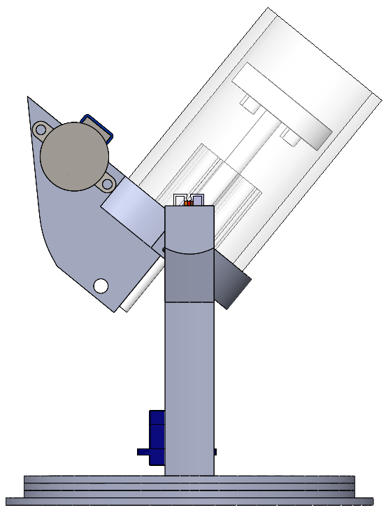
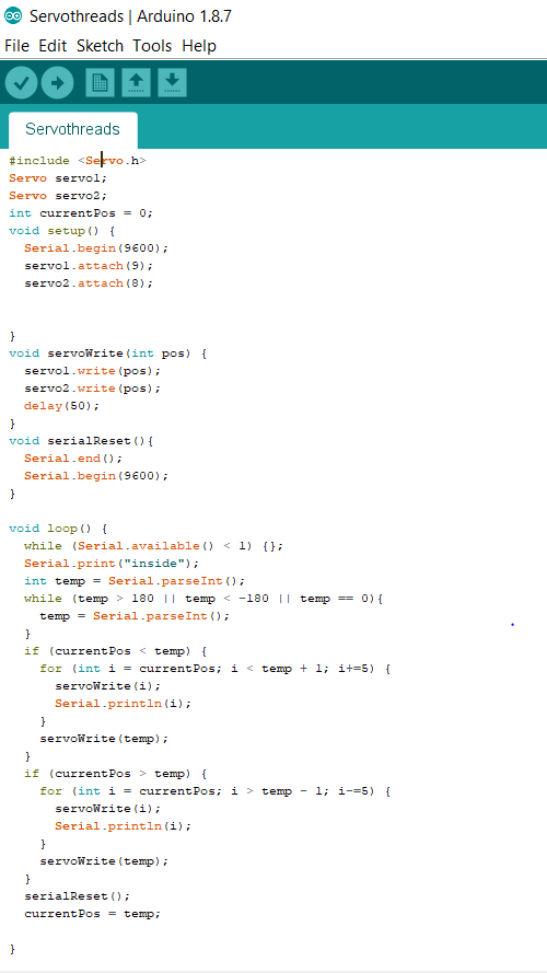
3. Servo motor advancements
Further advancements have been made on the two servo motors which control the y direction of the canon. The program reads from the serial buffer and makes sure that the input received is within the usable interval of angel values. The idea here is that
whatever angle we desire comes in the form of a serial buffer transmission, which is then picked up by this subsystem, or program.
Predicted risks to this approach is that the serial buffer may be cluttered with integers which are not desired y-angles, which might require further programming
to avoid. One idea to deal with this eventual problem might be to coat the y-angles in something called a flag. A flag is something which we learned about
in another course were packets of information sent over networks has a flag, which indicates when a packet of information starts and when it finishes.
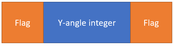
Figure: Flag illustration to avoid serial buffer misreads
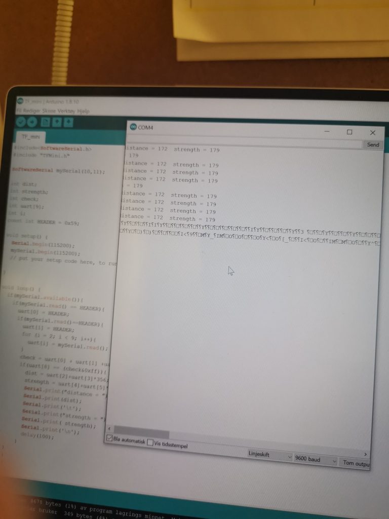
4. LiDAR
Since I struggled with Arduino mega 2560 and liDAR and the problem was that when I used to run the code, which was to calculate distance, then printed random character that had no meaning and as we see in the picture below.
After a lot of web searching, I figured out that to use Arduino mega and a LiDAR, you need a logic converter. I was still a little unsure about that problem, so then I got to talk to Steven Boss about the issue. Steven Boss was also not sure regarding this problem. after a few minutes of searching, so he came with a solution that it is better to use Arduino Nano. Then I got borrowed it from Steven Boss, and we faced a new problem. This time my laptop didn’t support the Arduino Nano and needed a new USB port, which we got installed.