Software (Marius):
During this week i have been working on fixing a few bugs in the code, adding more functionality and cleaning up the code a bit.
Crane (Servo Motor):
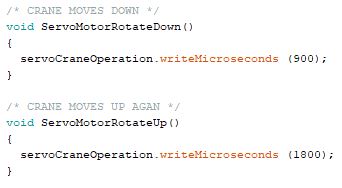
I first started with the crane which we want to be moved approximately 80-90 degrees. I first used a for-loop to be able to move the servo motor attached to the crane, but when testing this i quickly figured out that it did not operate the crane as intended. The regular servo motor which normally comes with the Arduino worked fine with the for-loop code, but the servo motor we had chosen didn’t. Therefore, i added .writeMicroseconds(time) instead, and it now works as we hoped.
Below we can see the functions for operating the servo motor both up and down.
Crane (Soil Moisture Sensor):
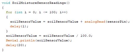
After the crane has been moved down the soil moisture sensor should activate and start recieving data. The soil moisture sensor is attached at the top of the crane which will result in the sensor getting in touch with the soil in the plant. I used the code as follows to be able to get correct sensor readings from sensor. From the test i did last week, i found out that the soilSensorValue will contain values from around 350 – 1040, where the lowest value indicates that the sensor is in contact with pure water and the highest value is dry soil.
Crane (Water Pump):
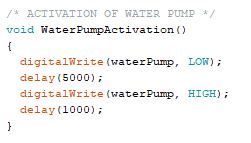
Initially, we had some problems getting the water pump to operate as we wanted. Firstly, we had the pump, gear motors and Arduino card attached to the same battery which led to a few problems when the code for the pump got activated. After some testing we decided to add a relay module and a battery for the pump on its own. The pump worked perfectly after doing this. The pump uses some time to be able to get the water from the tank and all the way up to the crane which is why it’s being activated for 5 seconds. The reason why it’s set to LOW at the beginning is how it is connected to the relay module. Unfortunately, we only got one of connection sides of the relay module working which means that we have to activate the pump by setting it to LOW instead of HIGH.
Crane (Merging all the different crane functions):
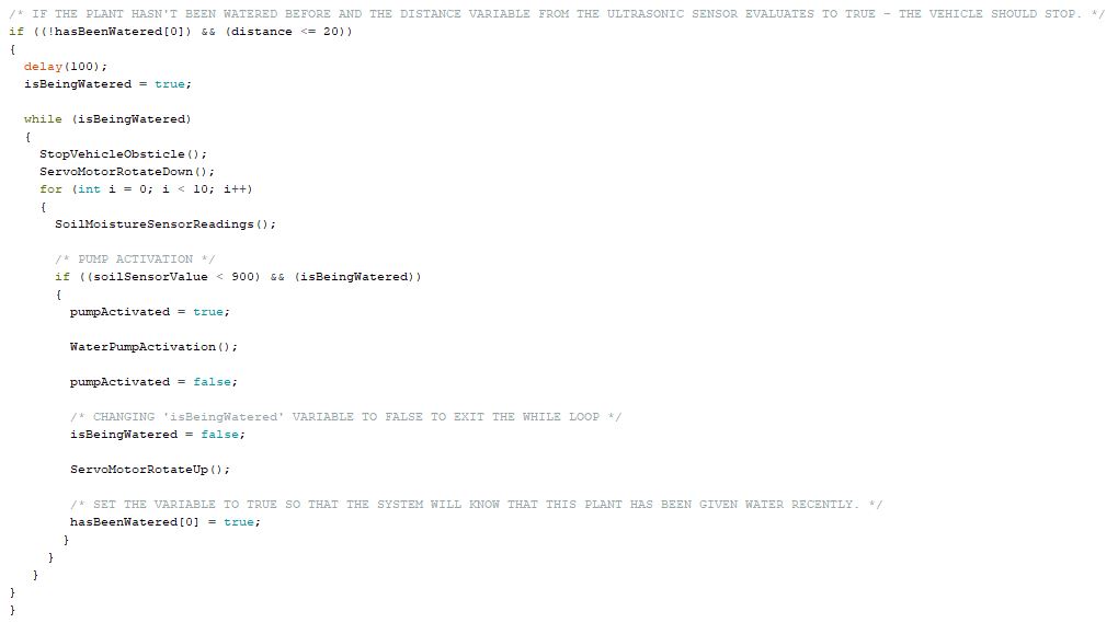
The final step on the crane was to get all the sensors working together. To be able to achieve what i intended, i had to use a few boolean datatypes. First, the system will check if the distance between the vehicle and the plant is less or equal to 20 cm (used for testing) and check if the plant has been watered before. If this evaluates to true, the vehicle shall stop and rotate the arm of the crane down to the surface of the plant. I then created a for-loop to limit the amount of sensor readings from the soil moisture sensor to 10, since we found during testing that 10 readings will be more than enough to get what we want. If we get readings from the soil moisture sensor below 900, the water pump should activate. After the execution of the water pump code, the servo motor will activate, rotating the arm of the crane back up again. I used an boolean array to check if the plant has been watered before to be able to perform watering procedure on several plants. The code need some adjustments to be able to do this and will be adding this during the testing phase.
The video below show how the crane will work with the code in Figure 4.
System functionality:
The illustration below shows how i want the system to operate. It should follow the lines by reading the line follower sensors and it should stop when the ‘blue sensor on the right side’ (the ultrasonic sensor) detects an object within’ 20 cm. If this happen, the code in Figure 4 should be executed and the vehicle will then move on until it detects a new plant. I hope to have enough time to add RFID readings on each plant so that the system can use this to check if the plant have been watered before.
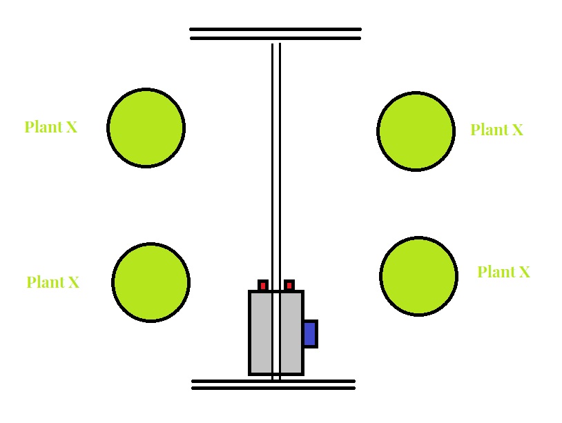
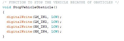
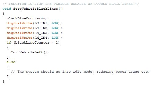
When the vehicle detects to black lines the vehicle shall stop by executing the following code (figure 7). I’m using two different functions to stop the vehicle. The first function (figure 6) will only be used to stop the vehicle when it should stop because the ultrasonic sensor detect an obsticle, and the other function (figure 7) is used when it detects two black lines.
The blackLineCounter is initially set to 0 so when the vehicle first detects a black line on both line follower sensors, it should set the blackLineCounter to 1 and turn around. The vehicle will then move back to it’s initial position and the ultrasonic sensor will detecting plants on the left side of figure 5 and executing the code in figure 4 again. When the system again detects two black lines it will stop and increase the blackLineCounter to 2. The system should now go into an idle mode where the power usage is reduced. Hopefully, I will be working on this feature the next week if i have enough time at my disposial.
What have to be addressed during the next week(s):
The mechanical engineers are currently finalizing the final system design and the parts will hopefully be ready for assembly by the end of next week. This means that i cannot do any more system tests before we have assembled all the 3D-printed parts. Therefore, i will be spending some time on adding some code for the features below and do the testing when the system have been assembled.
- Adding functionality / adjusting the code so that the system can perform water procedure on several plants (maybe adding RFID tags to check each plant?).
- Adding power saving mode when the system is done with the watering prodecure.
- Adding clock module or clock feature to be able to make the system to into idle and wake up after a given time.
Mechanical (Shadi and Per-Terje):
This week we worked on the redesign of the large and small battery packs and making space to hold them in place on the lid. We also continued to design the outer cover and we faced some issues where we didn’t have a printer that had the ability to print as large enough as the cower size. So we came with the idea to design a split cower to print half and half.
Electrical (Erlend):
Spent this week soldering and buying some equipment like wires, etc. needed for our system. Soldered together the batteries that I had planned out to try out in practice, before the mechanical students make a more permanent battery holder.