Gaute
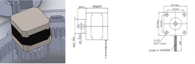
We finally got the technical drawings, with physical dimensions, for the stepper-motor this week. So, I made a model of the stepper and put it in the assembly. Did also make the gear to connect the stepper to the glider ring.
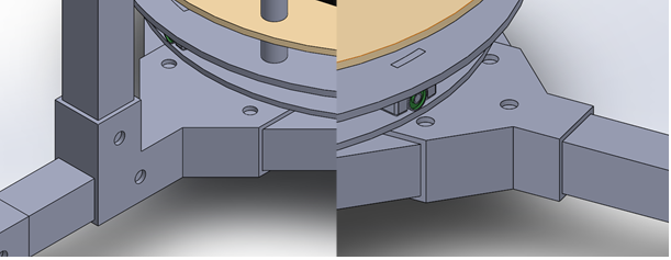
I also worked some more on assembly-blocks for the frame. The plan is to 3D-print the blocks so the physical assembly will become easier because we won’t need to weld anything. And it also gives us the opportunity to have the frame in aluminum and not steel. That could possibly save us a lot of weight, without the expense of the strength.
Halvard
This week I have continued to do material tests and gathering the information gained from those tests. I have not been able to finish all the tests due to working on other subjects this week.
But I will put up some of the data gathered this week, but in the next weeks I will make a bigger document presenting the information gained from this study.


This is one of the treatments we are considering using in our system. The heat treatment the material will go trough will be to make sure that we are fusing the layers together, but for some materials it will be an annealing process. In the case of PLA which is a semi-crystalline polyester thermoplastic it will shift from a mostly amorph to a crystalline product, this will give us more strength and durability. However, there are some disadvantages in this method. The PLA will slightly change form during this process, this is why I have printed 10mmX10mmX10mm cubes so we can map out the deformation in X, Y and Z- direction, but that will come next week.
Nicholas
I have spent this week working on setting up the Raspberry Pi. Starting off, I needed to install OpenCV and TensorFlow Lite. Our goal is to create our own model in TensorFlow then convert it to TensorFlow Lite so a good starting point would be to get the default example running on the Raspberry.
BOM:
- Raspberry Pi 3 B (1GB RAM)
- 16GB microSD card
First off, this is an older Raspberry and performance is therefore not great to put it lightly. However, the setup process is the same regardless of Raspberry Pi version. There are many guides available on this topic, but ended up using these videos (https://www.youtube.com/watch?v=aimSGOAUI8Y&t=302s and https://www.youtube.com/watch?v=ylnjXbcNLJU). First off I downloaded the latest image of Raspberry Pi OS. Using Etcher I then flashed the image to the SD card. After installing the SD card into the Pi and going through the standard start up procedure I turned on SSH so I could remote into it. So far so good.
Now comes the fun part and that is troubleshooting. Even though troubleshooting can be really frustrating sometimes it’s one of the most valuable lessons one can have and it often helps giving a better understanding of the system. As I think troubleshooting is so important I want to spend some time explaining what my problems were and how I went about solving them.
First of was the issue of a “Low Voltage” alarm constantly flashing. As the PSU I used is more than capable of supplying the needed current I couldn’t quite figure out what the issue was. It should be noted that the Raspberry Pi have been laying around for several years now and ESD damages are not out of the question. Unplugging all peripherals, including the screen, seemed to do the trick.
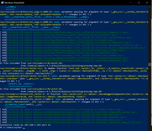
The next issue I faced was when trying to compile the code. When starting I used all four cores to compile the code. This worked fine until I reached files around the 78% mark. I guess these files were substantially larger than the ones previously compiled. After looking more into the issue I found out that the problem was that the Pi didn’t have enough RAM and as such need to page files on the SD card. Since the SD card is super slow this took a while and it simply couldn’t keep all four cores fed during the compiling. Running the make command again, but this time with “make -j1”, and only using one core worked as all the data could be loaded into the RAM fast enough for the CPU. In total the compiling took over 3 hours to complete.
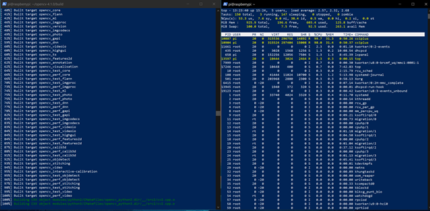
With all this downloaded I got the script to run on the Raspberry and could get some testing done. The first thing I noticed was the abysmal performance which likely could be attributed to the model only running on one core instead of all four. The RAM usage wasn’t very high so it should be able to use more than one core. This is as far as I got this week so I will need to spend some time next week and see how to improve the performance on the Raspberry.
To end this blogpost is a short video showing the current Raspberry Pi’s cooling solution to help out the struggling power regulator during load.
Anders
This week I have tried to implement MVVM pattern in the Windows Forms application controlling the puck passing machine. This has proven harder than anticipated because of general problems getting the serial communication between the Arduino code and the Windows Forms application to run smoothly, as well as some issues wrapping my head around the MVVM pattern in general.
The MVVM pattern is a model where we split the code into several layers which in turn makes it easier to expand and test our application later in the lifetime of our project. The architectural pattern facilitates the separation of the GUI and the back-end logic.
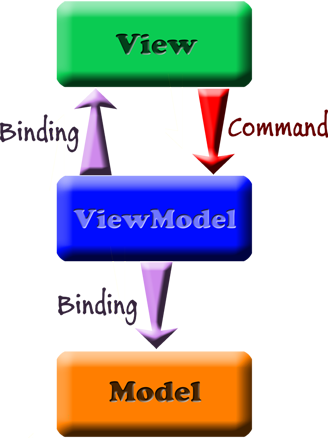
MVVM stands for Model – View – ViewModel and represents the different layers of our application.
Model
- Refers to the domain model or to the data access layer
- Domain model is the representation of real state content. (Object-oriented approach)
- Data access layer is the representation of content. (Data-centric approach)
View
- The GUI, what the user sees and interacts with
ViewModel
- The viewmodel is an abstraction of the view that exposes public properties and commands, meaning this is where all the functions and logic behind the application is done. This in turn has a binder to the view which automates communication between the view and the viewmodel.
Implementing this pattern will make future expansion and modification of our codes much easier and hopefully we have a good groundwork in place for future improvement when it comes to a control application now.