Software (Marius):
Since there was a lot of work (assignments and deadlines) to do in my two other courses, i had to prioritize this during week 6. Therefore, i didn’t have to much time to work on the project in this course.
In week 7 i started working on a state machine diagram to be able to see what the system is supposed to do in different scenarios and this would help me understand the programming needed throughout the development phase. There will most likely be made changes to the system during the iterations in the upcoming weeks and therefore, this state machine diagram might not be 100% accurate. But in the current state of our system and development process this is basically how it works.
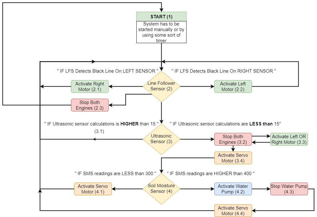
State Machine Diagram:
- When the system is started both gear motors will be activated.
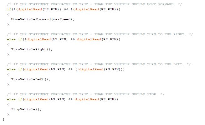
- If one of the two line follower sensors detects a black line on either side it will act according to this. If it detects a black line on the left side, right motor will be activated so that the vehicle will be turning left (2.1). If it detects a black line on the right side, the left motor will be activated making the vehicle turn right (2.2). The vehicle will continue like this until it detects a black line on both sensors which should cause the vehicle to stop (2.3), or until something is detected on the ultrasonic sensor which will be explained in the next step (3).
- The system will get continuously readings from the ultrasonic sensor which will be placed on either side of the vehicle (maybe a good idea to have two ultrasonic sensors, one on each side of the vehicle to be able to water plants on both sides?). Here we have to make some calculations to be able to make the readings from the ultrasonic sensor into centimeters. If the calculations is HIGHER than 15 cm (this is the number we used during testing and will probably be changed later) the vehicle shouldn’t do anything, and therefore continue reading the line follower sensors (3.1). If the readings are LESS than 15 cm both gear motors should stop (3.2). Then the vehicle will have to turn approximately 90 degrees left or right depending on which side of the vehicle the plant is on (3.3). When this is completed both gear motors should stop again (3.2). The next step is to activate the servo motor which operates the crane where we have soil moisture sensor and hose for the water attached (3.4).
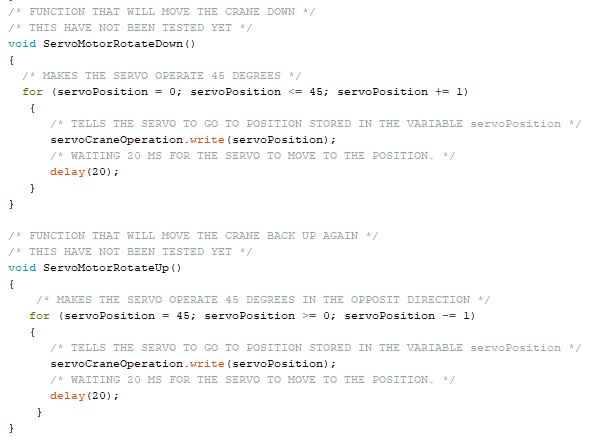
- On this step the servo motor have been activated, moving the crane approximately 45 degress (around this angle on our current prototype) so that the soil moisture sensor get in touch with the soil in the plant. If the soil moisture readings are LESS than 300 (using this number at our current prototype. This might be changed later on) which indicates that the plant is already moist (4.1), the servo motor need to be activated to move the crane back to its initial position, and from there keep following the line follower sensors. If the soil moisture sensor readings are HIGHER than 400 which indicates that the plant needs water, the water pump will be activated for X amounts of seconds (4.2) before it’s stopped (4.3) and the servo motor is activated to operate the crane back to it’s initial position (4.4). The vehicle will then continue following the line follower sensors until it detects another plants and the same procedure is applied.
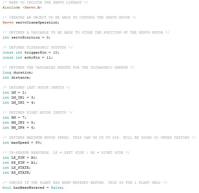
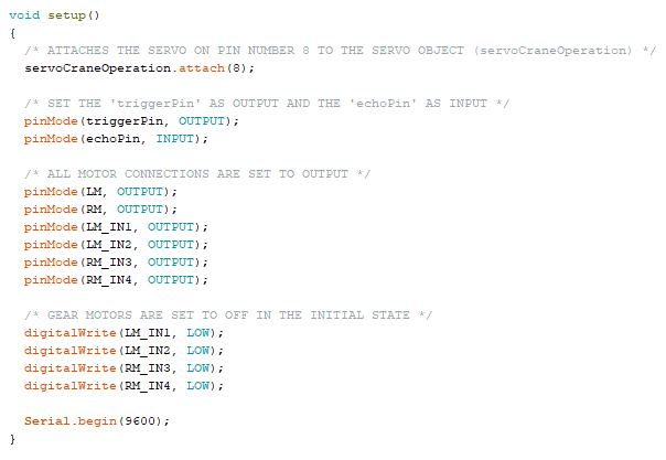
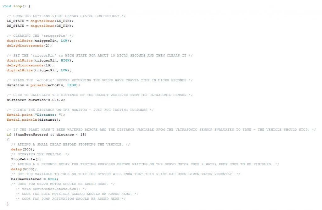
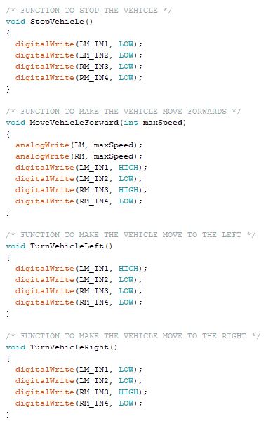
Programming based on the State Machine Diagram:
The following code is some of the code i have been working on to be able to match what should happen to the system according to the state machine diagram. I have basically got everything working up to step 3.2 in the state machine diagram so far, where the vehicle stops when detecting an object. The next steps couldn’t be done before the crane design was finished and 3d-printed, which was done at the end of this week. Therefore, i will be working on the programming and testing for the crane, the soil moisture sensor and water pump during next week (week 8: 12.10 – 18.10)
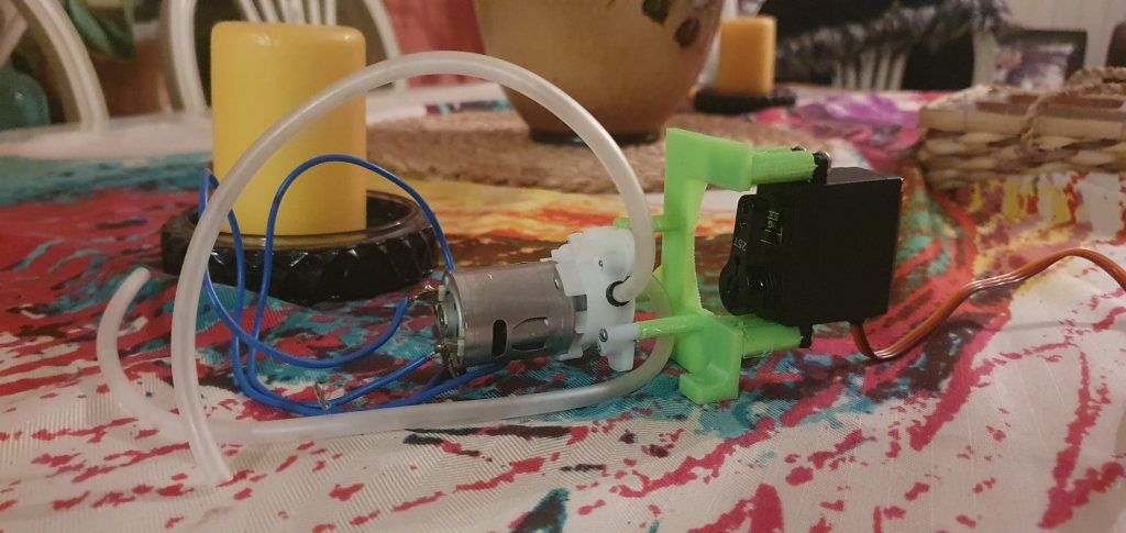
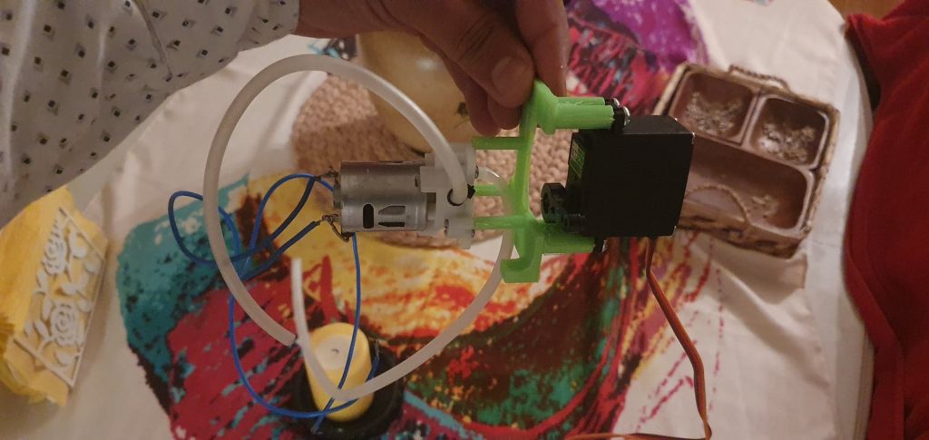
Mechanical (Shadi and Per-Terje):
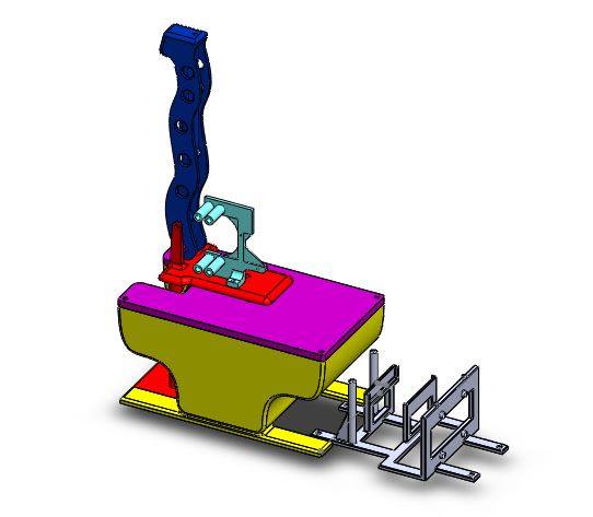
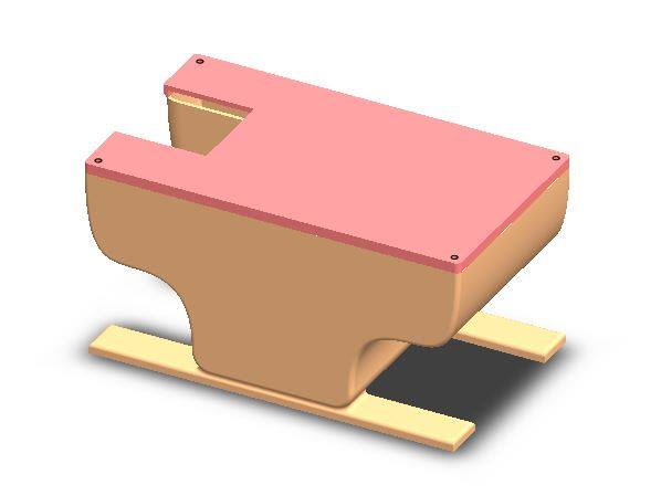
During this week we have been working on designing brackets for the sensors and redesigning and printing the new version of the crane top and crane bottom
All the parts for the prototype are finished, we have started analyzing the functionality of the prototype, we discovered some issues and started redesigning a new version of the watering system for plating to make it more compact and integrate the parts together.
Electrical (Erlend):
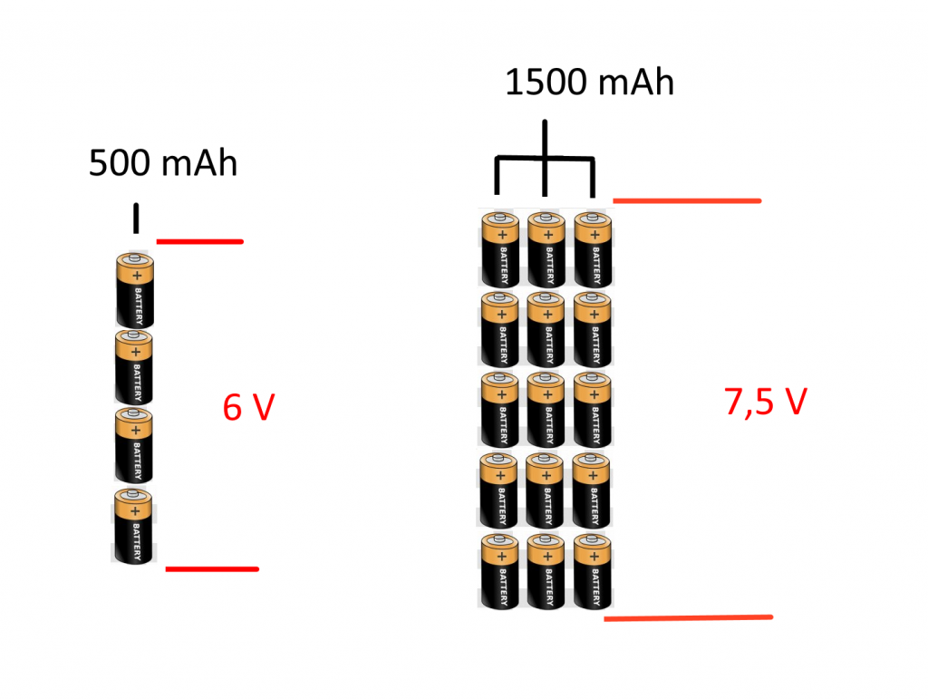
A lot of the time spent these two weeks has gone into the research of the power situation of our project. The initial thought was that the 12 V RC battery we acquired earlier in the process would drive the entirety of the system, more specific the DC motors, the water pump, and the arduino/sensors through a 5 V voltage regulator. But when wiring up the voltage regulator it quickly burned out caused by the high inrush current of the RC battery. This coupled with a previously overlooked incompatibility between the battery and the pump, led to a complete redesign of the power system of the project. So instead of just having just one battery of 12 V, I have decided it will be best to move forward with two separate batteries. The first battery will consist of a multitude of aa batteries, more specifically 15 batteries in a configuration which is illustrated in the figure below. This 7,5 V battery will drive both the pump and the two DC motors. The second battery will consist of 4 aa batteries in a configuration which is illustrated in the figure below, this 6 V battery will drive the arduino/sensors.
I also did some rudimentary tests on the two different soil moisture sensors we had, to see which one would be the best fit for our project. The two different soil moisture sensors tested were the FC-28 and the HW-390. Found that the FC-28 were superior in multiple aspects, such as accuracy, speed of measurement and quality of design.