Nicholas
Electrical:
All the parts we use to test are subject to change before the final implementation. They do however work in the same logical way so the software should stay more or less the same even if the parts are changed.
Current BOM:
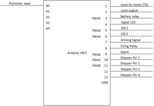
- Arduino Uno
- Potmeter (50KΩ)
- BYJ-48 stepper motor and driver board
- Simple button
- 10KΩ, used as a pull-down resistor (Only pullup internally)
- 3 LEDs
- Relay module
- 250Ω resistors (to protect LEDs)
Started to connect all the electrical components together to test a base version of the software.
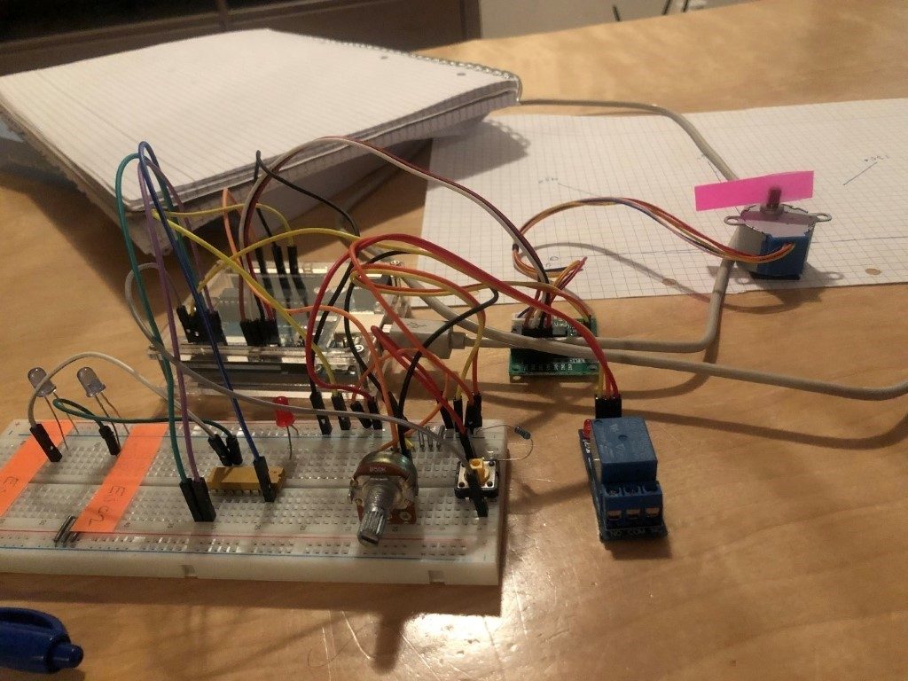
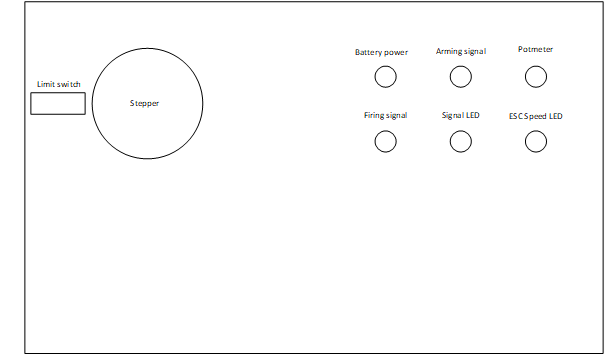
However, to make it easier to transport around we decided we wanted to make a box containing all the components. We could then use this box to test all the features of the software while waiting for the real machine to be constructed. I’ll come back next week with more schematics and drawings as well as more detailed reasoning for the different components we ended up using.
Lots of debugging the Arduino code.
Anders and I have spent a lot of time this week debugging the Arduino code and adding functionality. I’m now going to use the next few paragraphs to highlight some of the issues we faced and how we ended up solving them.
Get stepper to work:
First of was to get the stepper to work. As most are probably aware of, steppers is based on relative positioning which means that the stepper itself doesn’t know where it is. Only the µController that sends the steps knows where it is supposed to be. Due to this we needed to add a homing/calibration function that would set the stepper at position 0 when the switch was activated. The limit switch is attached to an interrupt pin (pin 2) to make sure that the 0 point is registered as accurately as possible.
Another issues was that we needed to convert between degrees and steps used for the stepper. For testing purposes we are using a BYJ48 stepper motor. If we look at converting degrees to steps here we will notice a problem. The total number of steps for this stepper is 2048 (more or less, some searching points to the gear ratio being different between different manufacturers). That means that 1° = 2048 / 360° => 1° = 5.6888 steps. Since a stepper only can move whole steps we would lose 0.6888 steps for each degree moved. If the stepper is asked to move from 0° to 90° that would mean it would miss a total of 61.2 steps or roughly 10°. Due to this we added an extra function that tries to add the extra steps missing based on the degree target. While still not entirely accurate it’s considerably better than the original solution.
One could of course ask the question why we wouldn’t simply send steps over the serial connection instead of the and eliminate this whole issue. Our reasoning is that by creating this abstraction the user, either a person or an program, doesn’t need to know what kind of stepper and gearing that is used. The µController will be programmed according to parts used and then it will simply convert the incoming degrees to steps for the stepper that is used. If we would have sent steps both the client code, currently Python, and the µController would have to be updated.
Other stepper implementation:
We deiced to use the standard stepper library as it’s easy to use and works out of the box. However, as is described here [1] the Stepper.step() function is blocking. As we would need the Ardunio to perform several tasks more or less at the same time we couldn’t send all the needed steps at the same time. Instead we placed the Stepper.step() inside a while loop that continually increments it by 1. By doing this we are able to read new serial data and shift the target for the stepper without it needing to reach its original target.
Serial.parseInt() problems:
So, moving on to our next problem. Slow response from the serial read function in the Arduino code. While doing some testing I noticed that the stepper used an unusually long time changing direction after new coordinates were given. Due to it being late I was tired I decided to just turn a LED on and off with a simple line of code in-between. Using this method I noticed that the LED was staying lit for far too long when Serial.parseInt() was called. So, I went back to the documentation to try and find out how the function worked and why it would be so slow. The answer to the first question is that the Serial.parseInt() function reads the input until either a non-number data is registered or until the timeout reaches 0. The way I implemented the serial communication means that I do not send any ‘\n’ (newline) after each message. Due to this the first criteria for the Serial.parseInt() is not met and a such it will wait until the timeout reaches 0. By default the serial timeout is set to 1000ms, and this explained the long delays I noticed. By using Serial.setTimeout() and setting the value to 10ms I greatly improved the response time of the stepper.
Summary:
We have done a lot of work this week on the software for the project and we have now established the necessary groundwork. This means that the all the core software components now are in place and we can start to create new branches and add features. This is a huge milestone as it allows us to more independently work on different components. We can now start to optimize the Ardunio code, or look at how to implement OpenCV and YoloV3 on a RaspberryPi or another small computer. I also need to start working on the electrical schematics and wiring diagrams.
Referanser
| [1] | «Arduino,» [Internett]. Available: https://www.arduino.cc/en/Reference/StepperStep. |
Anders
Testing Launching Mechanism
Thursday last week we tested our firing mechanism prototype, this prototype is scaled down 50%.
The issue at hand here is still the fact that we aim to accelerate something more than ten times heavier in our final product, but for now we are pleased with our working prototype and can now start testing more and add functions as we continue working on our project.
Debugging, debugging and more debugging
The past couple of weeks have been used mostly to debug our base code to get to a point where it works without to many bugs and we can zero in on things we want to change or add.
GUI
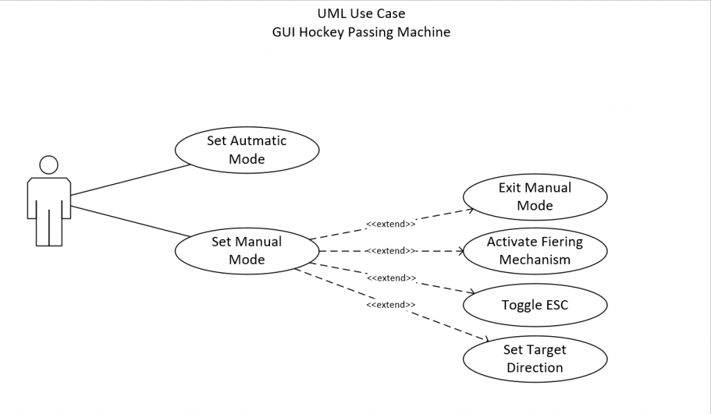
For our GUI (Graphics User Interface) I have started working on a windows application to do the serial communication with our Arduino Micro controller. The plan is to have a working application up within the end of next week for use when testing our system further.
We also plan to have some sort of information sent back to the application to be able to spot trends and optimize our physical equipment.
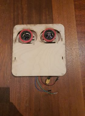
Creating two modules for software testing
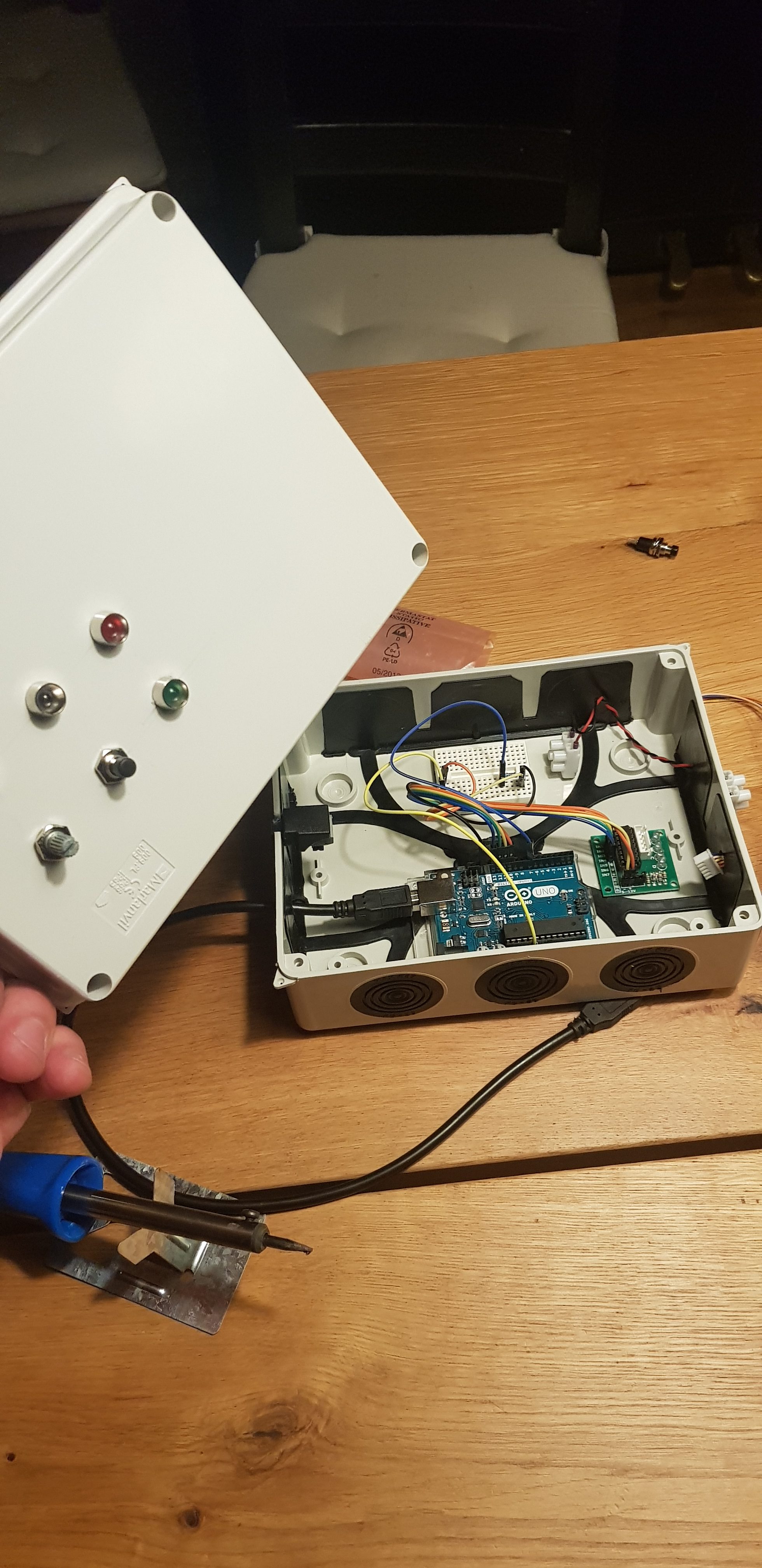
This weekend myself and Nicholas sat down and made two identical modules whit steppers, switches and lights close to what a finished product is imagined, the reason for this is that we now can work remotely and still have the same test condition which makes it much easier for us to help each other when were not in the same room.
Gaute
Week 37:
17.09.20:
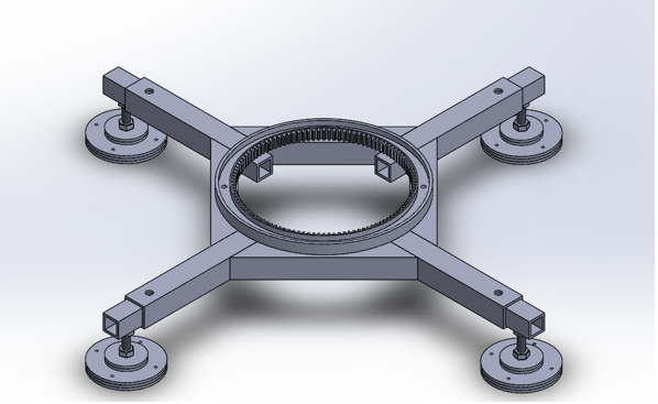
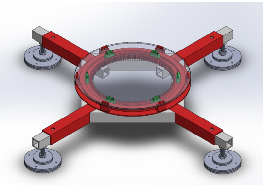
Fourth gathering. We met up at laserlabben to do some prototype testing on the hockey puck launch-mechanism. Did some major adjustment on the platform about the size of the rotation-hub.
19.09.20:
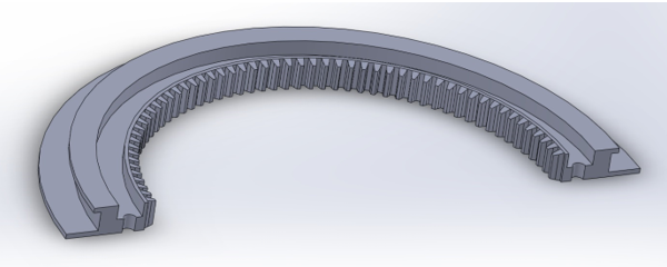
Worked further on the rotation-hub solution. On the previews version you can see that we don’t have anything holding the launchpad and platform together in vertical direction.
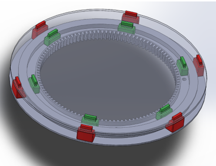
The solution was making some tracks on the vertical side on the glidering, so that we could assemble some blocks to keep the launchpad-plate on the glidering.
20.09.20:
Me and Halvard had a short meeting on discord where we discussed some challenges we had stumbled upon. Among other things the new vertical-lock design I made yesterday. We came to the conclusion that we could remove the green blocks since they are locking in both horizontal and vertical direction making the green blocks of no use. So nest week I will continue the work on the glidering.
We also made a little colour-suggestion just for fun.
Halvard
3D printing, research and assembly
This week I have been doing mostly assembly of our first iteration and research on the materials and manufacturing techniques which we are going to use especially with regards to friction reduction and making the puck glide smooth out of the firing mechanism.
We found out that we will have to do something to reduce the friction between the hockey puck and the plate it will initially glide on as well as in the magazines. Since we have scaled everything 50% down, we also had to 3d print the pucks to get them to fit. This allowed us to research different materials as well as different manufacturing techniques.
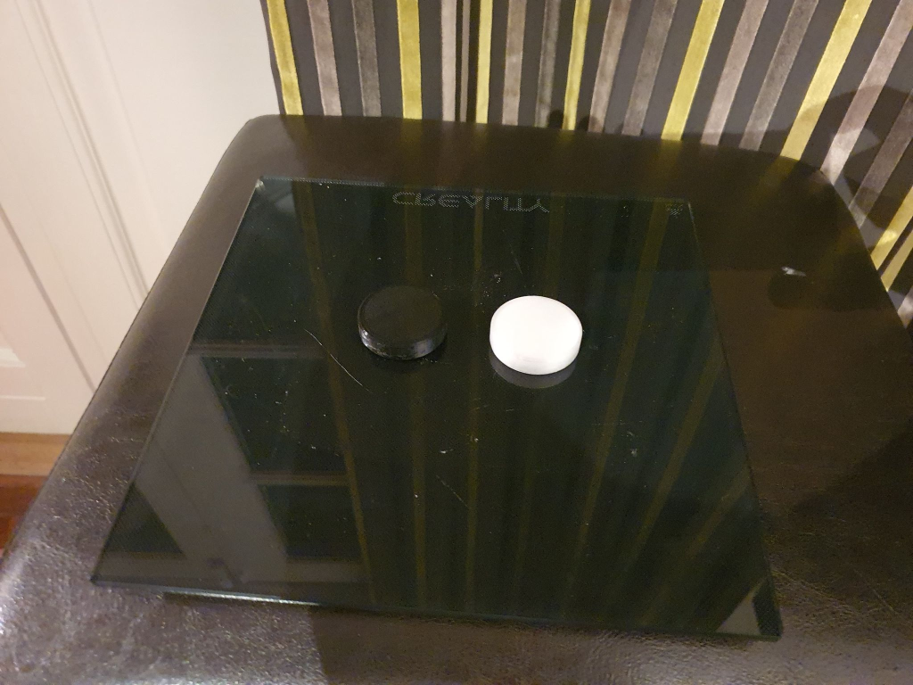
The build plate
I started using plates with BuildTak which has a textured surface, this in turn will leave a textured bottom on the final print. This is why I changed over to a glass plate, this will leave the prints with a glass smooth bottom.
The materials and the manufacturing techniques
Some of the materials we are considering using is PLA, TPU, PC, PET-G, ASA, ABS, Nylon as well as other materials which will for example be used as support materials, PVA etc. I also started to look at techniques for making the plastic glide even better. One thing that I was researching this week was the ability to make plastic parts that contain a few ml of a lubricant. This was done by making the g-code print the middle layers at 20% speed making it easy to apply the lubricant with a needle inside the infill structure. This made the oil seep extremely slowly out between the plastic layers, lubricating the bottom of the part. One could also manage the rate at which the oil flows by reducing or increasing the amount of filament extruded at the top and bottom layers. Before any of this was printed, I researched the chemical resistance of the thermoplastic I was going to use by looking up the technical datasheet. After this I tested a small length of each of the filaments that I was going to use to verify that it would not react with the lubricants.
In the coming weeks Gaute and I will produce our own values of the materials we are using in the materials lab.
Production of our own co-polymer
After doing some research about annealing 3D prints for higher strength we started to think about ways to manage the warping the annealed parts will experience. We found an article [1] about a filament that is almost warp free after annealing. It is based on a polycarbonate core with an ABS shell. This can be produced by 3D printing the filament with a dual extruder and then making sure that the filament isn’t bigger than the diameter of the heat-brake. We have not yet started with this, but we would like to do some research on this in order to find out if this can give us more usable and lasting prints.
Non-planar printing and other slicer settings
When we are talking about 3D printing, we are usually talking about doing operations in the 2.5 dimension. This means that an 3D object will be turned into many layers of the 3D object’s cross section stacked on top of one another. This can turn into a problem especially if there are curves on the top of the model.
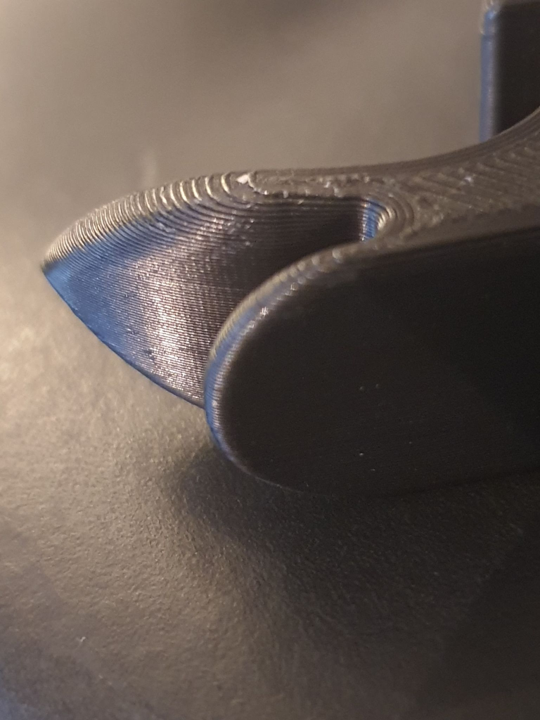
To reduce the effect this will have on the top surface with regards to friction, I have started to modify a printer as well as the slicer program to allow us to have a non-planar printing surface. I will update further when we start printing using this method. For the full code and documentation on the non-planar slicer see this link [2]
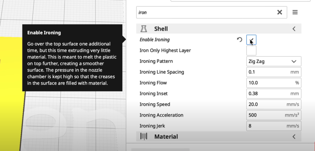
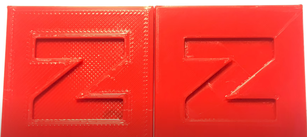
Ironing and initial layer horizontal expansion
In one of the slicers I use, Cura to be specific you now have the option to iron the top surface of the print. This will almost remove the typical 3 printed lines and marks on the top of the print. This will also make the top layer smoother and this will result in less friction between the pucks when they are stacked on top of one another in the magazine assembly.
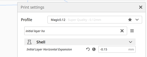
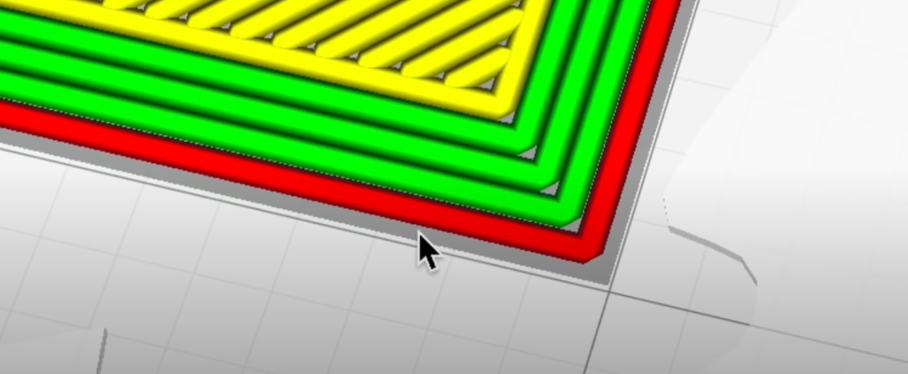
The initial layer horizontal expansion option is a way to reduce the squishing effect that the nozzle has on the first layer. This was especially important when we were printing the wheels that are going to drive the puck. I found that the bottom layer would be extruded 0.3mm wider than what was designed. Since Cura has an option for this I just divided 0.3mm by 2 and plugged in -0.15mm in the slicer settings. This means that the fist layer will be printed 0.15mm smaller than the next layers.
Referanser
| [1] | [Internett]. Available: https://scitechdaily.com/new-army-multi-polymer-filament-tech-turns-low-cost-3d-printers-into-high-tech-producers/. [Funnet 18 09 2020]. |
| [2] | [Internett]. Available: https://github.com/Zip-o-mat/Slic3r/tree/nonplanar. [Funnet 17 09 2020]. |