Nicholas;
As we started the project, we had a lot of setup to do to ensure a good workflow. We ended up using GitHub as our repository as it’s easy to use and helps us document the work we do. Here is a link to the project git repository if anyone is interested in seeing the files used. Please note that there are some test files there currently. https://github.com/NichoPellic/hockey_passing_machine
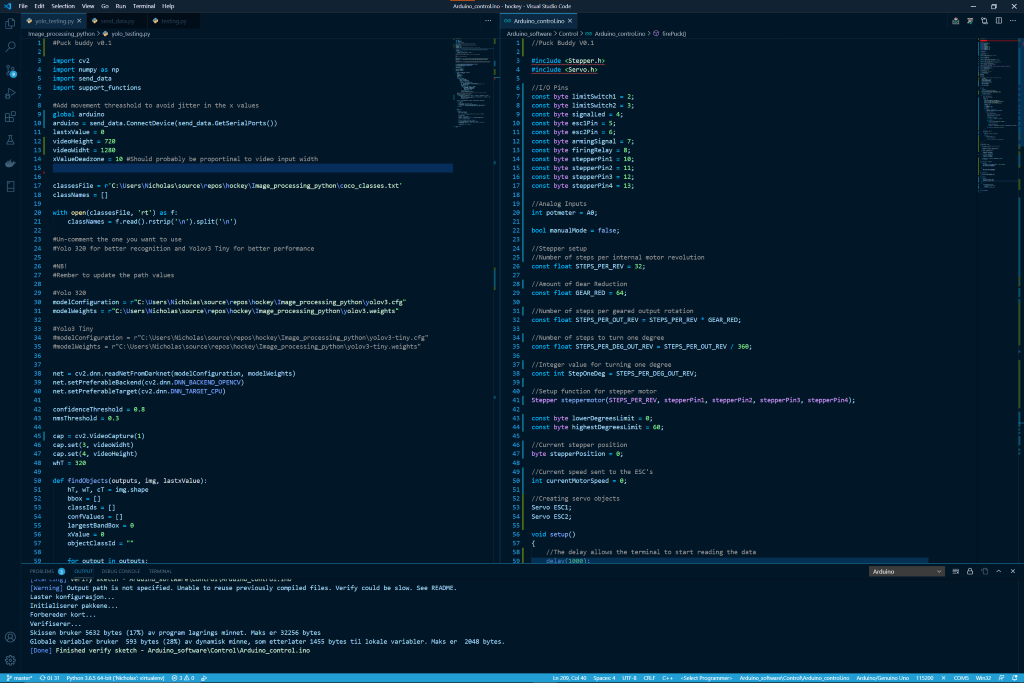
As for other tools I personally decided to use Visual Studio Code as my code editor. The main reason for this is that it’s a very lightweight code editor that at the same time supports a lot of features you normally would except from an IDE. Another reason is that by extensions you can make Code work for any programming language and as our code base will be a mix of several languages this is a big plus. Also, Git is built into the application which means less programs/terminals needs to be used in order push and pull coding changes.
After all was setup if and we had some brainstorming we started to look into different code to create a proof of concept. We started off by creating a basic system hierarchy model to split the system into workable parts.

As for the software, Anders and I sat down and created this basic data flow diagram used to highlight how the data flows between the different components.

Anders;
Following Nicholas I also choose to use Microsoft VisualStudio Code for all my programming this semester, as he so neatly explained above it can be used seamlessly between different languages and have GitHub functionality integrated by the use of extensions.
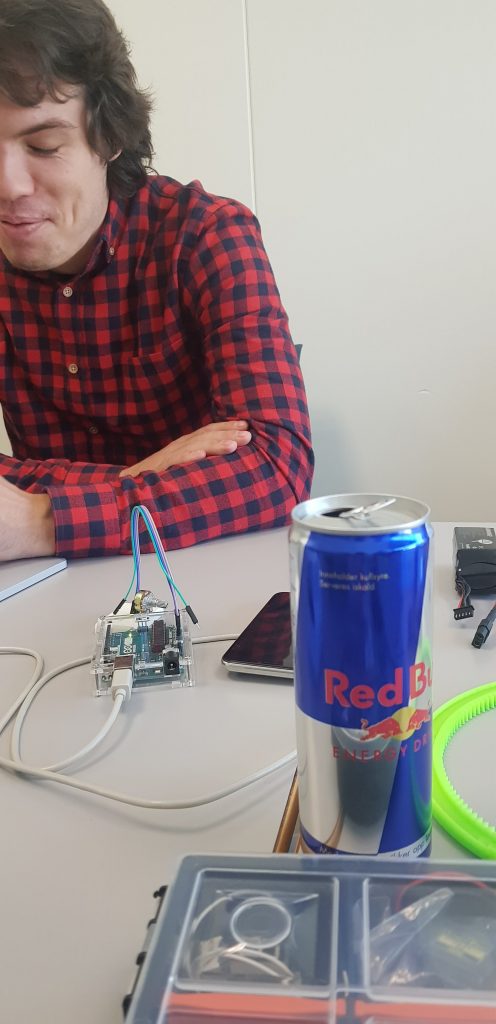
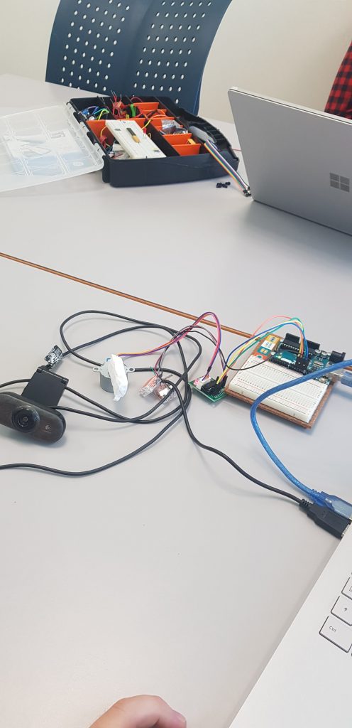
The past weeks Nicholas and I have started making modules for controlling servos and steppers and started to merge them as they came out as we wanted.
Other that that we have looked at a solution for image recognition using YOLO3 witch is a open source image recognition software, so far we have looked into using a RaspberryPI to do the image recognition computing but we might converge on a NVIDIA Jetson based on performance.
Halvard;
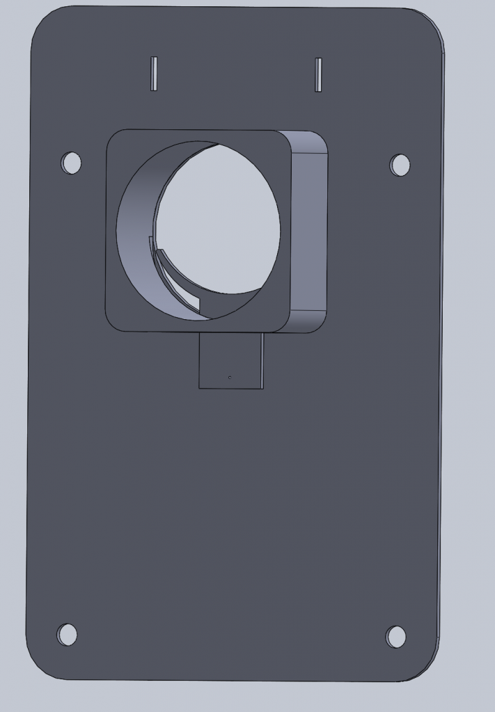
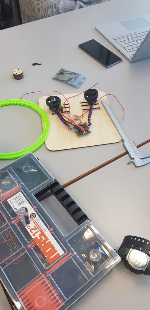
We started in CAD to get a rough overview of the product we where going to design. We looked at all the mechanisms that we needed to produce for the product to function as intended. Then we started to model them in Solidworks, our first model was just a proof of concept with mounts for the engines, ESC, magazine-feeder (img bellow) and magazine-mount.
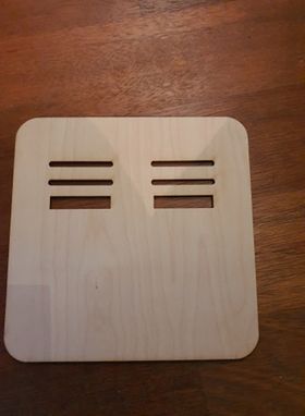
After this we produced some 2D-drawings of the bottom plate so we could cut them out with the laser-cutter. We choose to produce the bottom plate from plywood in the start to get a physical model to understand the workings of our proposed solution.

We then started to look at the forces that will act upon the product in use as well as the effects of gravity. We found out that we needed to find ways to manage all the forces the product will be subjected to during use. To do this we will need to do some more in-depth research, for example a FEM-analysis(Finite Element Method) of the model, which we will do in the upcoming weeks.
Gaute;
Uke 34:
20.08.20:
Brief introduction to what the subject is about, and what expectations the lecturers have for us students. We formed groups and started with the thought process of what we want to create during the course.
Our group consists of two computer students, Anders and Nicholas, and two computer students, Halvard and Gaute.
We searched the web for inspiration from similar projects, but did not find anything that we liked. Eventually it turned out that Anders and Nicholas play ice hockey and that’s how we came up with the idea of making an ice hockey puck machine that can shoot passes out on the ice. Everyone liked the idea well and saw good opportunities to get a good project.
Uke 35:
27.08.20:
Second gathering. We sat down to discuss further on our ice hockey puck machine. We machine guys started to draw a little what thoughts we had about possible solutions for frameworks and physical design. As well as discussing and gaining clarity in which conditions underlie the design, which considerations must be emphasized and functional requirements. Halvard and I shared the design between us so that Halvard takes care of the launch module and I take care of the frame.

28.08.20:
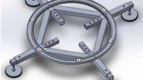
Started by modeling a bit in Solidworks. The idea here is that the legs should be adjustable so that it has increased stability while in use and takes up less space during storage. The paws can also be adjusted in height, possibly not necessary, time will tell.

30.08.20:
Worked a little further with the frame. Worked a bit to find a solution to the turn challenge. Think the solution must be to have a step motor mounted in the frame of the launch module that pulls the module around.

Uke 36:
03.09.20:
Third gathering. The mechanical engineering students received a brief overview of which assessment criteria our contribution to the project is measured according to. Otherwise, the day agreed to continue working on the project.
What was done today was that I changed the leg structure a bit so that I could cut down on the weight. Also work on making some friction blocks that keep the swing construction in the groove of the ring.

04.09.20:
Has divided the slide into six sections so that it can be 3D-printed.

Made grooves at each end of the section so that they can be mounted together. Prints a prototype of each track to test if it is feasible

05.09.20:
Printed some prototype parts to test if the concept can work in full scale. The ring is 50% of its original size, while the parts in the middle are full scale.

