Final 2 weeks
Mechanical:
Adithya:
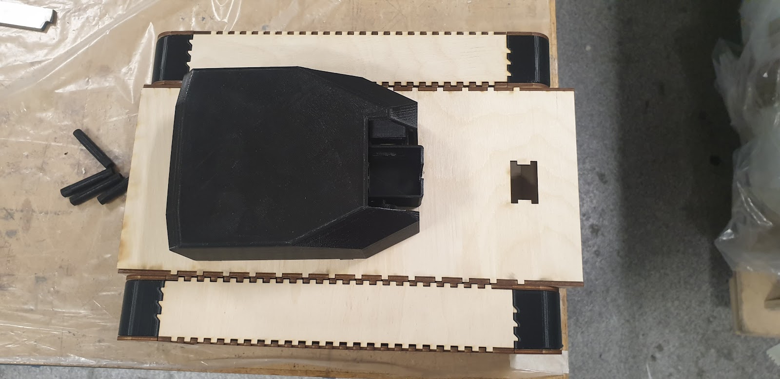
The first week I printed out the necessary parts to assemble the body of the main body of the tank, including the side panels. This allowed to begin assembling the body of the final product as shown below. I am satisfied with how it looks as it resembles a tank and the width to length ratio is also pleasing to the eye. The side panels are attached to the main body with screws and can be easily removed with a drill. Progress was slow this week as I had to focus on the upcoming exam. The physical model now has the necessary holes and slots for the parts which will be connected to the body and due to prior testing the clearance should be sufficient for the parts. The body shown in the pictures, without carbon fiber coating weighs 900g, which makes out goal for having the final product way under 3 kilos plausible.


The second week started with 2D drawings of some of the more complex parts and preparing exploded views and bills of materials for the assembly and sub assemblies. This is also shown below.
INSERT 2D TEGNINGER
Exploded view of the suspension sub assembly: https://www.youtube.com/watch?v=LHrGh3YeXXg&feature=youtu.be
Exploded view of the main assembly:
Exploded view of main body:
Through both weeks small adjustments had to be to the suspension parts to ensure they fit with each other and the main body, and during the second week all parts necessary for completely assembling the suspension are ready.
In addition, I intended to have a carbon fiber shell around the main body which would have taken an immense amount of time to get the polished carbon fiber finish. Instead it was suggested to me that I try laser cutting planks with carbon fiber attached to them but after testing this was shown to be unrealistic as the glue holding the carbon fiber to the plank evaporated due to the heat of the laser and would ruin the edges of the products. This would have been ideal if it had worked as it would have allowed for easy machining of holes and other indents I required. Instead we have to go for a third alternative. First I have to paint all the exterior panels black, and then glueing one layer of carbon fiber on each panel individually as a whole. This makes it a lot easier, even though it may take a bit more time than covering the entire piece in one sheet of carbon fiber. Carbon fiber coating will be for aesthetic purposes only. It will not replace any wood planks and therefore is a less important requirement. If I have time I will be adding carbon fiber.
After sanding and enlarging the holes in the 3D printed parts I assembled the suspension and side panel sub assembly. However, after attaching the belt with pre tension the ‘main lock’ part cracked as it could not support the forces in the x axis. This forced us to abandon the entire idea and attach wheels from the first prototype. This means we will have no suspension.
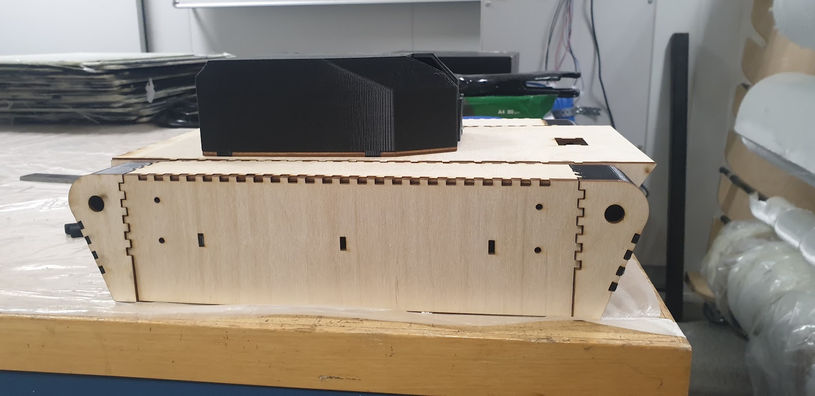
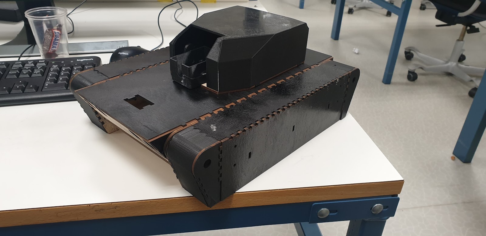
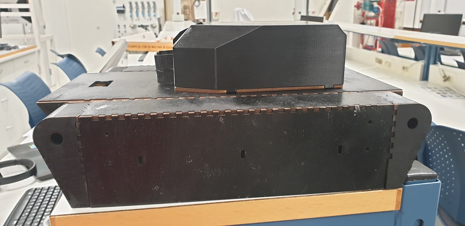
Tank after painting:
Bill of materials:

Lastly, using sheets of rubber from biltema we laser cut 4cm wide pieces and connected them together to get a belt with perfect length while having elastic properties to allow for pre-tension. Pre tension in the context of a tank is important as if the belt is loose the wheels may come out of its groove.
Reflection:
Overall I am happy with our tank. Ideally I would have liked to have designed parts which are realistic and can be machined in reality, however knowing our main resources are laser cutting and 3D printing many of my parts cannot be me machined in metal in reality . Secondly, we had a big focus on visuals. We wanted our tank to actually look like a tank and I believe we have succeeded in that aspect. I am also a bit disappointed that we were not able to implement a proper pellet shooting mechanism into our tank, but the main reason we did not pursue this was because the cheapest airsoft pistol using an electric motor we found was for 500kr and since we weren’t given any budget we weren’t willing to use that much money on this project. In addition I underestimated how much time 3D printing takes and how difficult it is to learn contraction/expansion in small parts when printed. Also I didn’t realise how much time I would have to use on other subjects and overestimated how fast I could work on the tank which left us with finishing the product in the last week, which was suboptimal.
When assembling and testing the suspension assembly in the last week, I discovered the “main lock” part that was 3D printed has good strength in the y axis when supported by the springs but it was very weak in the x axis. When the belt was moving the part could not support itself in the other direction and broke. This forced us to improvise and go to a much simpler driving mechanism and not use the suspension system. This was disappointing as I had hoped for the suspension to work properly. The printed parts all fit perfectly and required some drilling/sanding to allow for perfect fit, but due to the lack of strength in one component the whole concept wasn’t sufficient.
Jonas:
The first week we finished producing almost all of the parts necessary to assemble the tank, and then put all of the sub-systems together in order to have a black box where electrical components could be mounted and tested.
As previously mentioned, having a body made out of carbon fiber was the initial goal, But it turned out to be a process that takes way too long. Laser Cutting carbon fiber (glued on top of the wooden body) was also not an option since the glue couldn’t “survive” the laser. The only option was then to paint it, so it at least looked like the surface wasn’t made out of wood.
The polymer used for 3D-printing the tower of our tank happened to be black, so painting the main body and side panels black is naturally the way to go, to ensure a somewhat even look a design.
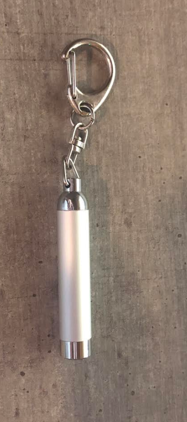
The box used to house the laser looks the way it does because I originally planned to place the following laser pointer in it:
Since we wanted to remote control the laser, we decided to go for a stripped down version. This made the box a little oversized for its purpose but we made it work by melting a hole through the back and securing it to the mounts anyways. This means that the tower part of the tank is now mostly done. I might need to laser cut some small pieces to ensure that one of the stepper motors are fastened to the main body, but this is a process that won’t take long at all if needed.
Exploded view of the tower assembly:

Video:
Video of Re-assembly:
Reflection:
From the start i really wanted an end product that looks like a downscaled version of the real thing. I think we managed to accomplish this quite well with the given resources and time. One thing i think the whole group have learned, is that simple tasks may take a long time to finish even though they seem simple. An example could be the 3D-printed parts we made. Since the production process of these parts involve melting and solidifying different polymers, tolerances have to be somewhat generous in order for parts to fit.
I would have really liked to implement some more mechanical components/features into this vehicle, but there really isn’t that much room for any more wiring or curcuitboards in the main body.
I would have really liked to have a main body made out of carbon fiber, but this turned out to be impossible because of the time left and the shape of the tank, further proving my point that there really isn’t as much time as one would think.
Computer:
Arpan Sharma:

So, this last two week went on waiting to get the assembling of the last and final part for our Tank. The part was looking good and everything was discussed with the other students. We just had to patiently wait for every part for our tank was completely assembled.
Since the machine part did not finished printing the tank before in the last week before the final deadline which was approaching. So, we didn’t get time to fix or test drive the tank before some days before the due date, but it works pretty well.
As you can see the tank is looking great, but it was sad that we had to drop the belt on our tank so it didn’t work in the end.
In the end we did have to use the same function as prototype two, so that our tank could perform at all. But one thing we didnt take to notice was that the weight on our tank became too heavy. Which in the end kill our battery of our tank pretty quick and most big problem, the pressure on our tank was too heavy. So, in the end it could not perform as well as it did in the previous week, so that was sad and disappointment. But that’s the truth of the reality. After all, we have to be realistic and not forget to ignore Newton’s laws. “If the apple hit Newton’s nose, Newton’s nose hit the apple”. To much weight pressure made it not easy to move in the end. But we in the end made it work, group work is really important. Without it was not possible to assemble our tak complete as it is today. It has many functions beside the maneuvering, for example the tank would not drive without the card reader connected to the tank.
Coding in C++
The coding challenge was really fun and I learn so much from it. Like working on arduino parts such as motor drivers, ultrasonic sensor, bard and wiring connection, Bluetooth-module etc. learning everything wasn’t easy tank and I had many times frustrating time when my code isn’t working as I wished. I did get help from my teacher a lot and of course by my group Rahmat and Kiriasan.
To connect to Arduino mega wasn’t easy as it was in the first year, but the most difficult part was to understand the logic of the coding. Especially when I was working the Ultrasonic sensors. I had to measure the correct distance ( with ruler) of the object and make sure the Arduino car could detect movements of the object and obstacles in the path of it. I had difficulties with bluetooth module to. It wasn’t easy as it should have been to code it and make sure it could perfore correct manually driving and turn on the led light when bluetooth was connected to the car.
It took me some time before I could crack the code. But in the end all worked fine out.
Conclusion ( Arpan)
In conclusion, we learned a lot from our group work. It was really exciting to work in a group and individually. I learn so much from the experience I experienced in this semester. It was both challenging and difficult times, but without it, how can we not learn. We worked well in the group. And had many opportunities to learn different ting from it.
By tackling the various tasks and challenges did I get the opportunities to explore the outside of my comfort zone, which wasn’t an easy task at all. Like working with electrical parts and building the prototype, or experiencing the physical behavior of the car which I had no experience of before. Like the saying goes if you don’t burn your finger or get headaches when working, then you are not working hard enough.In the end, I learn so much in this project which made me so much better in the field of engineering( the electric -the machine and computer science engineering). And not just that and this has aroused my interest in working more on this in my free time than working for a study project.
Rahmat Mozafari:
Assembly
After looking into the fire and aim system since last time, I mainly worked on the assembly of the prototype as the facial recognition system was done. Assembling the second prototype went quicker than last time as i already knew how to do it, but still, it took quite a while to get all the wiring right. After testing and fixing and wiring I implemented my autonomous code within the system.
Even though the main body of the prototype was done, I was asked to make a new one which I felt was unnecessary. But as new parts where finally being 3D printed and had to be put onto the tank a new prototype had to be built as they weren’t compatible with the previous one. Therefore I spent the last days before the deadline disassembling the previous main body prototype, so that I could make a new one. Whereas the earlier prototypes had been using wheels for movement, this new one was going to have a suspension system with belts going around them to move around. Unfortunately while I was putting together the 3rd prototype of the main body while these parts where being prepared we found out that the 3D printed suspension were way too frail and would just snap if we were to use them on the system. Because of this we decided to make use of wheels as we had done on the previous prototypes.
Autonomous movement
Even though this 3rd prototype was going to use wheels, the mechanical engineers wanted to use a belt so that it would look more like a tank. So i had to make changes to the autonomous movement system so that this version of the tank could move around like a tank would. As the previous prototypes had been using wheels to move around, the autonomous movement was made to steer like a car instead of a tank. I spent a lot of time doing a lot of adjustments to the code so that it would steer properly. To move the tank like a tank instead of a car i had to make each side of wheels work in tandem. Where if the tank was to turn towards the right, the wheels on the left side had to move forwards and the wheels on the right side had to reverse. I had to spend a lot of time getting this right, as the way it previously could maneuver set the standard for how I wanted it to move now.
Reflection:
I had a lot of fun doing this project. Throughout the course of putting this tank together i’ve been able to develop my technical skills, not only in regard to programming, but also in assembly of parts and electrical wiring as i had to do a lot of that in this project. I got to work with openCV which was new to me, and created a face detection system with Kirisan which i’m very happy with. I also took a lot of responsibility upon me to make this system work, as I did the electrical part, programmed the autonomous movement from scratch and put together all 3 of our main body prototypes.
Testing video of our project.
This video is taken by Kirisan Manivannan
You can find the code for this project here by clicking to this link.
Jens Paulsen:
Calibration
After last blog post, I found that the way the variables from the detection system sent to the servos worked, was sending the location of pixels on the window of the videostream/ camera image. Because I knew I could not work with pixels as they were to accurately move the servos, as the pixel values are just their location on the screen. I thought of converting pixels over to meters. I attempted to do this by measuring me and Rahmats face in cm and then check the height and width of our faces the program printed in pixels to get a pixel-to-cm approximation, but quickly scrapped the idea as it would be a poor solution overall i thought.
I tried then to figure out how to take measurements (pixels) from the face recognition system, operating in a 2D space, and how to use that with the servos which are operating in a 3D space. The idea here was to use the law of sines to get the angle of the servos. Doing the pixel-to-cm approximation of a users face, mentioned earlier, to then approximate the users height. Where after looking it up is somewhere around 8 lengths of their head. By multiplying the value in converted from the pixels to cm with 8 i would get and approximation of the persons height. But thought this solution was not got enough if i wanted this system to be accurate.
Therefore I went to talk with Steven to find out how I could do this. After discussing some possible solutions i thought virtual depth calibration sounded the best. Since we would not have an actual projectile to fire, the “firing” part of the aim and fire system would be a laser instead. And because of this I wouldn’t have to consider the trajectory of a projectile. Doing virtual depth calibration sounds easy in theory, where i would make the servos point to each corner of the camera image where at that point the servos would gain their extremum angles. But to do this it would require camera-laser alignment where the servos at their resting position would point to the center of the camera image Doing this would prove more difficult than i thought.
OpenCV
Since the virtual depth calibration required the laser to touch each corner of the camera image, i had to be able to detect the laser to know where it was. The detection program used to detect persons in this project is openCV, which is why I used that also. A lot of time was spent learning how to use it. And after working on this for a while, and multiple iterations later, the laser detection program could pretty accurately pick out the laser pointer on a white surface such as a white t-shirt or a piece of paper. However this program would be very depended on the lighting in the room. This was because the values given for lower and upper bounds for the color red to be detected was static. This meant that values given to the lower and upper bounds could let the program detect the laser very accurately in a well lit room and detect much more that i wanted in a darker room, and vice versa. Given more time I would rather try to have them adjust to the lighting as to avoid inconsistent detection because of the lighting.
The next issue I had was with the raspberry pi. When I first tried to run the gpio output to the servos within the openCV code, openCV would just stop until the servos where done, which meant they had to run as their own function or within the main function instead of running the servos within the openCV program. However, when I later got the code to run the servos would go crazy twitching and moving all over the place. After speaking with Steven again I learned the difference between a microprocessor (raspberry pi) and a microcontroller (arduino) and how that was related to the twitching and erratic movement the servos had.
To sum it up to the best of my ability, the arduino has its own chip for the clock rate which ensures that the signals sent to the servos are consistent, whereas in the raspberry pi it does not have its own chip for the clock rate, and furthermore has much more going on within the one CPU running the raspberry pi, which makes controlling the PWM signals sent to the servos increasingly difficult. So what was happening when I was running the openCV code earlier, the raspberry pi would constantly be working with the raspicam as often as it could constantly receiving signals and sending them. All the while the consistent clock rate of the servos at 50hz would be interrupted or missing its timing window.
Threading
The next quick fix solution to this problem was to try threading, which I also had no experience in, and after trying out a couple of different things the servos started to move smoother than before as each function operated on their own core. The problem now became how to make these two functions work concurrently. I tried both global variables and the queue library from multiprocessing where the main program operating at its own core would start the queue, the openCV function would set the “start” variable to 1 if the laser was detected, and then the servo function would get the start variable through the queue.get() function from the library. Unfortunately, this would only come into effect if the laser was detected on startup, and would not stop movement of the servos when the laser was out of view. I suspect this has something to do with the program never running through the main function more than once where the openCV function would always keep running, essentially making it impossible to stop movement of the servos without stopping the openCV program. I did not get the global variables to work within the threaded functions either, getting error after error with something that should be simple to do, but somehow would not work with my code. I’m pretty sure the reason behind this has to do with the threaded functions, but at this point I looked elsewhere for a solution to try something new as i was pretty frustrated with the current code and how this threading solution was just adding onto the already large pile of issues i had getting this program to work.
C++
All this time was spent trying to get openCV to work concurrently with the servos, and I hadn’t even started on doing calibration. Then I learned that opencv has its own camera-calibration program, as i did not have a prototype or anything to work on to hard code the extremum angles of the tank to bypass the need to calibrate the servos through software. With days away from delivering the code, I decided to try everything to make the openCV camera calibration code to work, but ultimately could not get past the error messages. Since the code was written in C++ i hoped the reason behind this was because our code was i Python, so i decided to write it in C++ in hopes of getting it to work.
Working with C++ on the raspberry pi was a challenge since I had never worked with C++ in a linux environment before and had to learn how to cmake, write CMakeLists, and then “make” a project. But after working non-stop and creating a new detection program in C++, it still wouldn’t work. Later I found out that I wasn’t the only one who had issues getting this camera calibration program to work with raspicam, and that someone else had created and posted their code on GitHub to specifically work with raspicam and the camera calibration code from openCV. So i cloned his GitHub repository and hoped that it would immediately work. Unfortunately for me, this code was written for openCV version 3.4.7, and our raspberry had version 4.0.0. I still unnecessarily spent a lot of time trying to rewrite the code in the repository and in the openCV core files were most of my errors appeared. Even though I made progress in the sense that I got past error after error, at some point I realized it would be futile to the program work this way as i had no end in sight, and decided to stop trying to make this code work.
I considered changing the current version of openCV on our raspberry pi to the 3.4.7 version, but I was now days away from the deadline, and it would definitely mess up the object/face detection code Rahmat and Kirisan had made, and probably other issues as well so I decided against it. The plan was then to hard code the extremum angles of the servos, bypassing the need to calibrate, however i would have to wait for the tank to be put together.
After putting together the tank I found out that the force that counteracts the movement of the tower portion of the tank would be gluing the bottom servo to the main part of the tank, which would close the tank all together and make any parts inside, including the raspberry pi, inaccessible. I tried then to do remote access so that i could still code with the raspberry pi while the inside of the tank was shut close, but since I don’t have the pro version of windows 10 that wasn’t possible. I was then left with a catch-22 where not gluing the tank shut would allow me to access the raspberry pi to code the servos, and gluing the tank shut would achieve camera-laser alignment and movement of both servos, but would not allow me to connect to the raspberry pi to code the program. Because of this we ultimately decided to just do a simple sweeping motion program for the tank essentially scrapping my part of the project.
Reflection
I’m happy with how final project both looks and operates, but disappointed that my aim and fire system could not make it into the final product. During this project I learned a lot. I learned about programming with the intent of delivering a final product. I worked with a lot of different libraries and through using these different libraries I learned how to use library documentation as a means to write code. This was also the first time using linux and programming within it which was a learning process as well.
As a team member I should have been more involved with the mechanical part of the project to avoid miscommunication with things like what parts i’m going to use. And I should’ve been more knowledgeable about the other programs taking place within the tank. Had I known more about openCV, the laser detection part of my program would not have taken so long, and the getting pixel locations sent to the servos would not come as a surprise either. Knowing how the program (face detection) works when my program is supposed to run within it, is just common sense in hindsight. I should’ve been more thoughtful of what kind of sensors i had to work with in the first place, as this virtual depth calibration was so dependent on camera-laser alignment. Had i known that from the start, then i could’ve been clearer about what parts I needed and why, which would’ve made hard coding a possibility long ago and would’ve made testing out my program easier in general. In the end im happy with what we produced as a group and I learned a lot about working together as a group throughout this project.
Kirisan Manivannan:
This course has taught me a lot of things. I have personally become a better system developer and have pushed limits more than what I have done before, the comfort zone has even been worked out. This course has helped me to understand the main purpose of an interdisciplinary project and a taste of the real project world. During this project there has been many smart and not so smart solutions, and many discussions.
The last week I have worked on the prototype along with the group and made improvements on my other tasks. I have also improved the wiring diagram and improved the autonomous driving code in team with Rahmat, to make sure that the tank drives much more perfectly and smoother than what it has done before.
My main task since the beginning of this course has been the OpenCV on raspberry pi, along with Rahmat. I started the whole process with downloading libraries and packages into the raspberry pi 2, with the operating system Desktop. The first and second week we only got errors and the pi denied downloading and stopped half a way. We used the time to troubleshoot and find out what the problem was and where the problem was. After a lot of researches and tests we figured out in week 4 that we were trying to download the latest version of OpenCV (4.1.1). We tried the older version (3.4.0) but it didn’t work. Then we changed the operating system from Desktop to pi Zero to try on that. Now in the last week the OpenCV is working fine but has a big delay time. We figured out very lately after discussions with Steven that raspberry pi isn’t the best circuit to run OpenCV on. But since I and Rahmat have worked a lot on it, we decided to use the pi, even with delay. Then we gave the raspberry pi with OpenCV to Jens, so he could transfer all of his work from aim and fire system over to the raspberry pi, to let it collaborate with the OpenCV.
During the OpenCV work I have also done other tasks, which are in different requirement levels. Since our tank’s name is Thomas The Tank, I have edited a logo for our tank which will be placed under the tank and created a python script to execute the song while the tank is driving.

The audio execution script I made is made in python, by using the pygame library. If we execute the program in terminal manually, the audio will start. But this is not what I want. I want it to start by itself when the Raspberry pi gets power. So, I made two solutions.
1. Include time library in the script and put a time sleep on around 30 seconds. And made the raspberry execute the program in boot.
2. The second solution is much better, which I found out after creating the script. If I enter this line of code omxplayer AudioFileName.wav into the .bashrc file, the raspberry pi will automatically execute the audio file when it starts.
Because of easiness, I went with the second solution by using a wired speaker. This wired speaker is shown in the wiring diagram. Link to the script (solution 1):
One of the A requirement was to create a manual steering system. First, I tried to do this by using RC controller, receiver and transmitter from my old RC helicopter. But this is like a “plug and play”, so what I decided to do is it create the manual steering system in Arduino with C programming. This purpose with this script is to control the tank by using an app (Arduino car) on the phone and control the tank over Bluetooth. I have tested the script to see if it is working fine, and it does. The plan has always been to integrate this code with the autonomous code for the tank, so we can do a manual maneuvering. But because of delays and postponed delivery times of the autonomous code we haven’t had the chance to integrate the code into it. But the Bluetooth manual steering code has been ready for several months now. Link to the code:
The last week now I have worked with building the prototype along with the group and creating wiring diagram for the raspberry pi. Since we didn’t have any electronic engineering student in our group, I tried my best to create a wire diagram that will gives us briefly view of how the system is connected together. The only thing remaining now is to show our product on Friday and make a presentation and a video of our tank in action, which I will film and edit on Wednesday. Link to diagrams, list of components and pictures:
Here is an external document with all the GitHub links from all the software students in the group: