Mechanical
This week we finally got a hold of two more 24V fans which serves our purpose of creating enough pressure under the board plate to make the disc “float” as we want it too. To see how this works in practice, watch the video below.
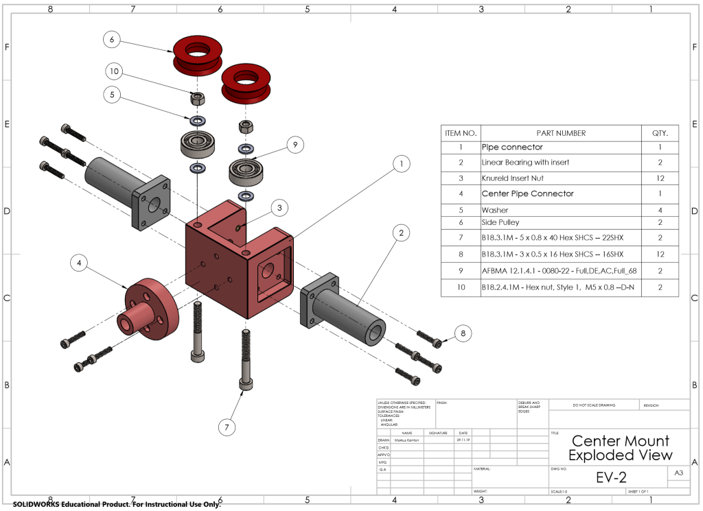
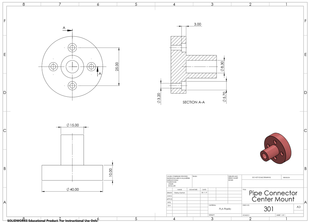
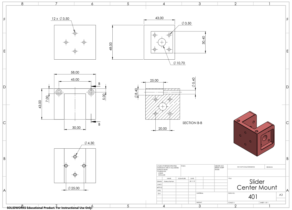
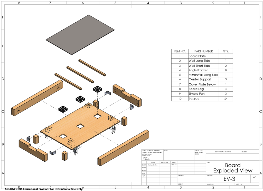
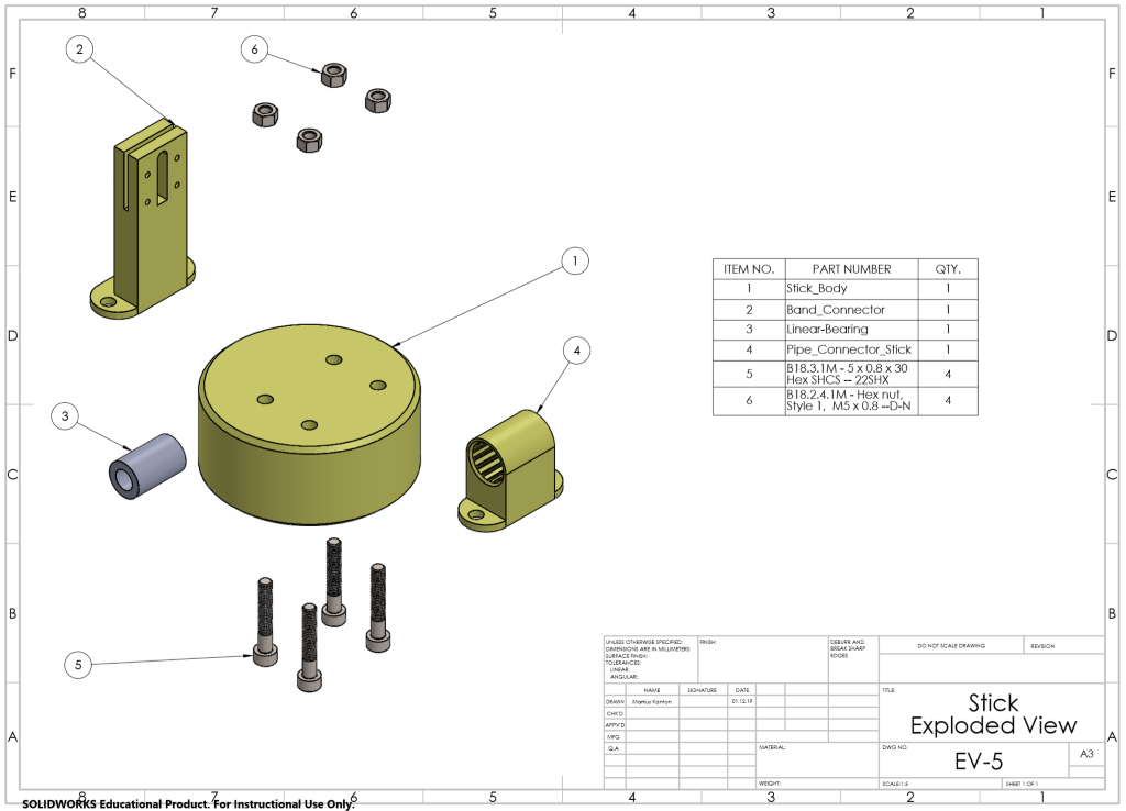
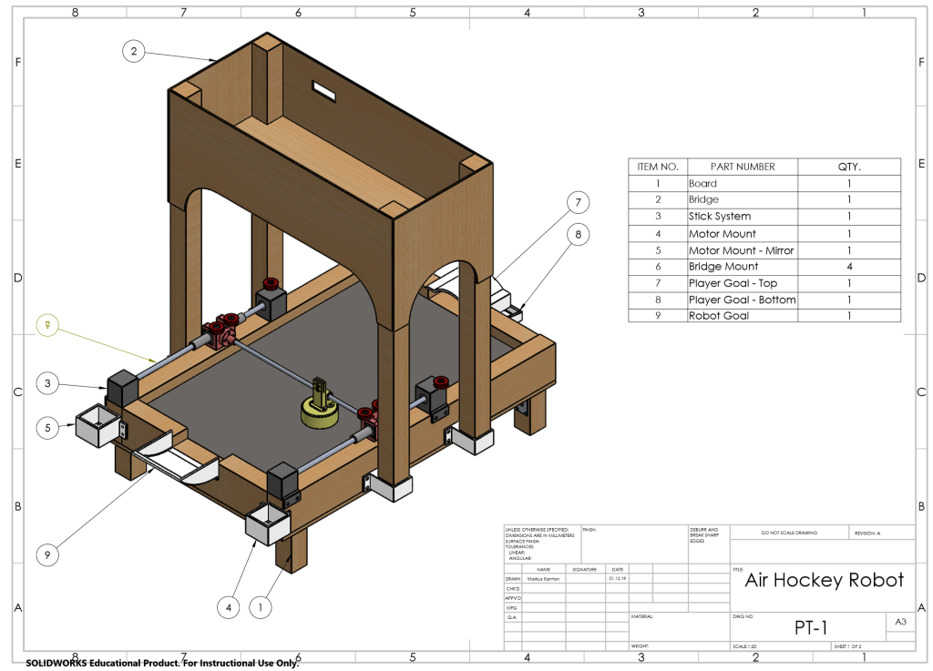
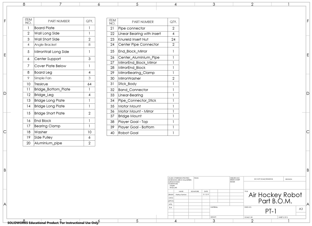
I have also used a lot of time finishing up all the documentation for the modelling. Making 2D drawings, exploded views and animation has taken a lot of time, especially since SolidWorks keeps crashing on the school computers due to driver issues. These will hopefully be fixed soon, but because of this I’ve had to create two of each part, with and without toolbox components. This has resulted in that the final model now is not that detailed. But all the parts where different toolbox products have been used can be found in the final delivery. Below you can see some of the documentation, hereof 2D drawings, exploded views and animations.
All the files for the 3D modelling, hereof: Parts, Sub-Assemblies, Assemblies, 2D-drawings, Exploded Views, etc. can be downloaded and viewed through this link: https://drive.google.com/open?id=1pQ7u_ta71Oe3a7rE9DYc6JI47PMYaHhT
The animations size are too large and is therefore uploaded with the youtube links above.
Electro
This week we were making some last changes in programming and combining our “electrical codes” with computer engineering coding, so that we removed all the bugs when we put it all together and finally, the whole (smart) system started working as we had planned in our first meetings at the beginning of the semester.
We had to smooth out the surface over the goal line, so the puck can cross the line and get inside the goal. The problem is, because we couldn’t get any bigger plate that could fit all over the air hockey ring and over the goal surface, we don’t have any air flow inside the goal and this surface has to be as smooth as possible.

Score counting works with the laser ray aiming into the photo-resistor. That means that when the disc crosses a goal line, the laser ray gets cut and the resistance is changed and the system detects the change and counts it as a goal.


At the end we screwed the joystick and final power switch on each side of the hockey table, in reach of a player. That way you (the player) can easily turn on the whole system and choose a game mode to play against the “unbeatable” computer.


Furthermore, Marc from electro has been working hard on the video, where the idea is to tell the story of a air hockey match set in Norway. Using this idea, the plan is to show a little bit of the whole process of the construction of the system, while the epic match between the human and the computer opponent is taking place. We will not be showing any clips here, as we want the entire video to be a surprise to go alongside the presentation on Friday!
Computer
Following the successful implementation of the basic defense functionality last week, we discovered a couple of bugs we had to iron out together with the electrical students for the system to truly work:
- While the functionality itself did work, it was far too slow, and was nowhere near unbeatable.
- The python program would frequently freeze when attempting to send data to the Arduino.
To solve 1), we began by researching if others had encountered this problem on the internet, at which point we found two prominent solutions: one was to reduce the amount of time the Arduino program waits for serial data, as it will default to 1000 milliseconds (1 second), and the other was to get rid of any unnecessary prints. By reducing the serial wait time using the serial.setTimeout() function, and reducing this to 10 milliseconds, as well as getting rid of some prints, we observed a dramatic increase in response time.
To solve 2), we likewise began our research, and found that this was not an entirely uncommon occurrence and could seemingly occur when the program gets stuck when attempting to write to the serial port. Here, we found that the solution was to flush the serial port prior to writing with the serial.flushInput() function, which will clear it before we transmit our new data.
Fixing these two issues have resulted in a reasonably competent computer opponent that we believe suffice as a proof-of-concept, but it is still not as fast as we would like. In an effort to further optimize our program, we began experimenting if the lighting of our board was static and uniform enough to use the default OpenCV color space: BGR, and if we could forego having to convert to HSV or some other color space. As we discovered early on in the project, converting the frame to the HSV color space necessitates a complex algorithm that is very performance heavy. After a couple of hours of testing different masks and lighting conditions, we discovered that without some sort of external source of lighting that could evenly light the board, BGR was a no-go. This is a result of the bridge darkening parts of the board slightly, as well as the player’s shadow frequently extending into their part of the board. We had ordered LED strips a couple of months ago, but these have not arrived yet, unfortunately. Consequently, we have decided to keep using the HSV color space, as this has given us the most flexibility and best results for our tracking with the lighting conditions we have.
Below is a video briefly demonstrating the system in action, after our latest fixes.
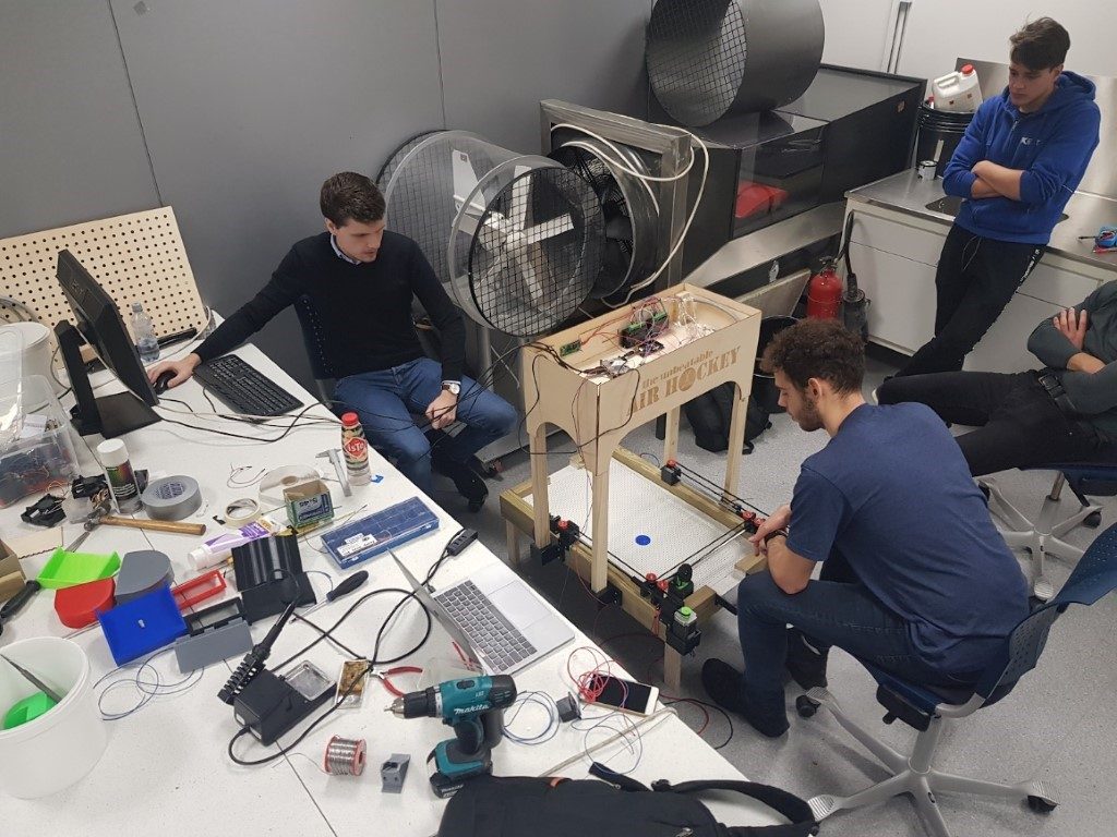
The last couple of weeks has been more hectic than usual, which is normal for a project that is coming to an end. The integration and the components coming together is the hardest part. No matter how good you think “your” part of the system works it is bound to meet some obstacles when subsystems have to start work together. Interfaces are challenging, mostly because it is then the different disciplines really have to work together as well as the fact that it is easy to lose the big-picture view of the system when working on a detail or a subsystem.
We also have been working on our presentation, graphical design, making illustrations, selecting material on what to say and who would say it. The time we are given for the presentation is short, so it is important to really think through everything and summarize the project in a concise manner. We tried to divide slides and presentation time equally among team members while maintaining the big-picture view of the project which is not an easy task. We are confident that we have done a good job on the presentation so far and will do it well when the day comes. If I would have to point out something that may (or may not) affect our presentation is the fact that we did not know the location of where we will present so the presentation style may or may not fit to the location/situation.
We also did some team building like filming together outside and taking a “road trip”. We have gotten to know each other through the course of this project, and we all feel it has been a good experience overall. It is interesting and educational to work in a team that is not only multidisciplinary, but also multicultural. It goes without saying it’s fun when you work on a project that is as cool as ours!