Petter
For those with access, check out Haptix2/Haptix/Assets/Petter Scripts for most of my work this last week.
This last week has been rough, I’ve gone from a rough prototype of a new Rubix script, which controls movement of the cube, to a relatively functional one who also works with leap motion and other members scripts.
I’ve gone through an insane amount of versions of our main applications to fix bugs and make sure everyone’s files are compatible with each other.
My rough script was based around a rigid object not updating, and leap motion is anything but stable, which means I had to do a lot of tuning to prolong signals and delay actions to make sure the scripts activate in the correct order, Rubix Layer Manager and Rubix Layer Animator specificly.
However we ended up with a working product and I’m really proud of the work the group has put in.
Herman:
My tasks or goals one might say of this project, was to implement a script for the microcontrollers that could receive and transmit data from unit to a microcontroller that than started a motor that corresponded to the finger that touched something in unity. I thought this possible to do wireless so that the user did not have restrictions in motion due to wires to the glove.
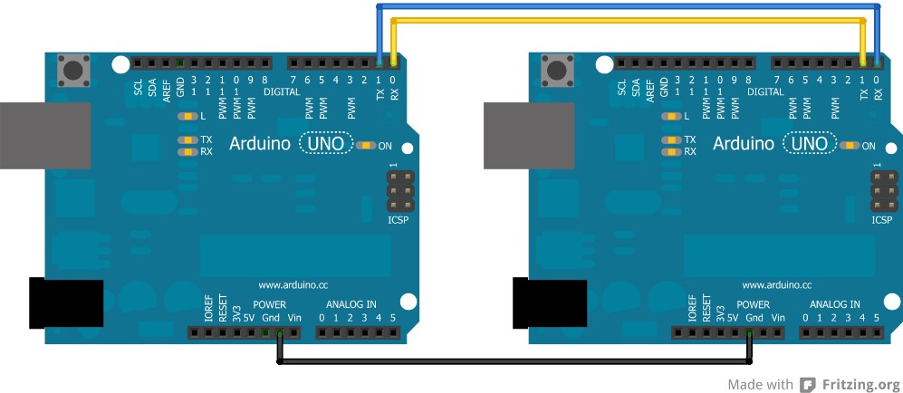
This required something to be at the transmitting end as well as the receiving end. Just to have gloves that work and so the others could have something to test with I began with the controlling of the motors through wires first, while keeping it as close to what the end goal would look like. So, her I used three units, one master and two slaves, that would be connected with RS-232 to minimize the wiring to the gloves, since UART only requires three wires to function. TX1 to RX2, RX1 to TX2 and GND to GND, as shown in the example below.
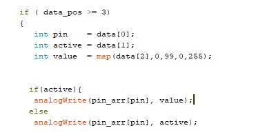
In this setup we have an Arduino Mega as the master, which isn’t a necessity that it has to be this model it was what I already had set up from previous projects. The slaves are two Arduino Nano units, this was chosen because of its size and because they are equipped with UART interface as well as 6 PWM pins (on 3, 5, 6, 9, 10). The PWM pins are necessary since we want to adjust the power of the vibration to simulate pressure on an object, the PWM pins or Pulse Width Modulation pins are equipped with timers that can pulsate the signal by turning on and off at a frequency from 0 to ~490Hz, decided by an analogWrite(pin, strength), where the strength vary form 0 to 255. Since we have decided to adjust the strength after the percentage of power, we must map out the values between 0 to 255. Under you can see the whole operation surrounding the decision-making of what actions to make.
The new microcontrollers are equipped with BLE modules that allows for wireless communication between the units, as well as connection from third party hardware E.G. a phone.
Initially it was the master’s job to decide whether the message was meant for the right or the left glove, but after converting to BLE the system now just repeats the message to both gloves and the gloves discard the message if they can’t anything with it. This is the reason we mention why discarding the master is an option, since it has no other real purpose than to validate the message and transmit it further.
To ensure that unity and the microcontrollers agrees on what is going on we had to develop a unified protocol for all the communication. This evolved over the course of the project as we needed more data and streamlined it further. At the beginning, when we only used one Arduino it consisted of Finger_id and S/T for Start/Stop this evolved since we only tested that the integration worked. Further we evolved it to consist of a start bit to indicate whether it was a legit message or not, as well as an end bit to announce we were done. This would look something like this start_bit(0) finger_id 1/0 (on/off) /n/n (end bit) e.g. 0 8 1 /n/n. When we came closer to a complete test platform we changed to fit with a strength- bit so that we could adjust the power of the motor. Here we also swapped the start ( { )and end ( { ) bit to be more streamlined for the system as well as for anyone monitoring the feed. It was also fitted to consume less data when sent. e.g. {8,1,99} which means finger 8 is active with 99% power.
Underneath we can see the code for parsing, as I also included in week 47.
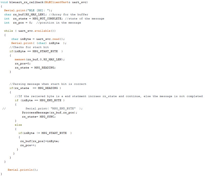
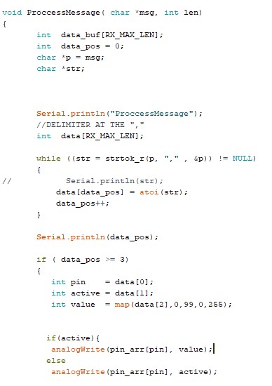
After parsing the message received the system determines which of this is what and puts it into the data array so that the script can execute what the message.
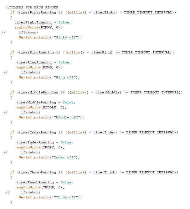
A problem we noticed when testing the glove was that unity had a habit of not recognizing when the finger where removed from the object and therefore, we added timers to ensure that they where shut off after some time without receiving any messages. I chose to put one on each finger, so that we didn’t shut down anything that weren’t supposed to shut down nor that the timer would reset for each finger when one finger where activated.
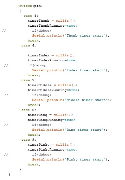
Initiation of the timers when the corresponding finger where activated
The actual timers.
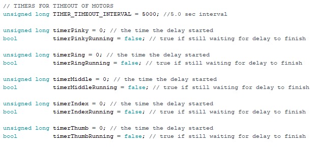
The TimeOut span are set to 5 seconds but are a subject for change.
As Daniel mentioned about if we could work further with the project or where to start over would it be an idea to send the status of each finger when something changes and not finger by finger, since this might cause delays or loss in communication due to an overload of messages received. Another idea would also to get rid of the master and make the computer directly communicate to the slaves, essentially removing one more link in the chain that could cause malfunctions. This could either be achieved through the PC communicating to the slaves on Bluetooth or attach WiFi chips on the microcontrollers making the system communicating on WLAN. Another point for further development would be to remove the leapmotion camera, equipping the system with sensors and integrate it into the HTC Vives tracking system by attaching their node on top of the glove, but this would be something that require more data engineering expertise, and therefor is something I couldn’t do as of right now.
Tom Erik:
We’ve decided upon using Leap motion, as our main tool for Hand tracking. Leap motion being a camera has a couple of major drawbacks. The most damning of those being field of view, meaning you are only able to track your hands wihtin the camers FOV, leading to always having to keep your hands in front of you. The second drawback being line of sight. The moment you attempt to cross your hands, or put one in front of the other, you will immedialty lose tracking of the covered hand. Immediatly pulling you out of the VR immersion. We’ve looked into technologies, and sensors to to combat these drawbacks, and improve tracking accuracies.
We landed upon using two kinds of sensors in our model. We noticed that leap motions sometimes has issues tracking fingers, we therefore arrived upon using strain gauges on the fingers to improve tracking specifically for the fingers. Strain gauges are variable resistors in which the resistance increase as it bends.
The second kind of sensor we’ve applied is an IMU. IMU’s are combined sensors, functioning as a compass, gyroscope, and to track acceleration. In this case, we’ll be using the gyroscope, and acceleration tracking. Tracking Hand position through movement (acceleration, and tilt (gyroscope), allows us to track the hands outside of the Leap Motion FOV, or while breaking line of sight. IMU should not be relied upon to be precise for extended periods of time, as it will lead to an increase in inaccuracy. Combining these two sensors we should be able to supplement Leap Motion well.
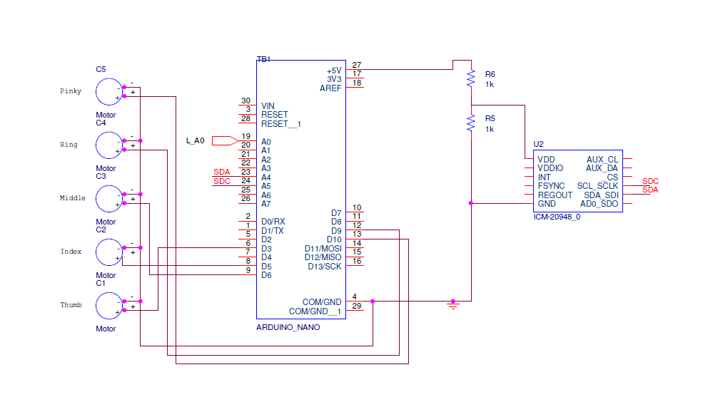
Left Hand
Since each hand is communicating independently, they require independent circuits. We’ve only considered our project as a proof of concept, and thus only obtained one IMU, and one strain gauge. All sensors are connected to the left hand micro controller
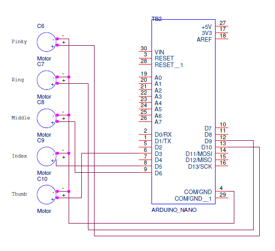
Right Hand
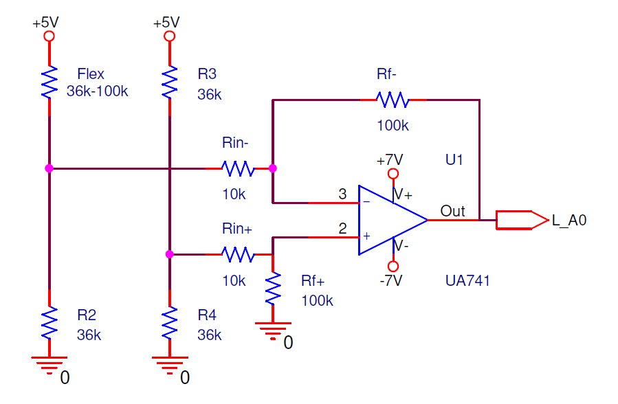
Schematic for Strain Gauge
Trying to measure values directly from the strain gauge through a voltage diverter led to only being able to read values upto 300 in the micro controller, meaning we’re only accessing ¼ th of available data points. Making it very natural to amplify the signal.
In order to obtain more precise measurements from the strain gauge a wheatstone bridge was utilized. In a regular amplifier circuit you amplify the signal in reference to ground, however with a wheatstone bridge, your reference is closer to the neutral state of the strain gauge, allowing us to increase how many times we amplify the signal, thus leading to increased precision. The issues with using a UA741 operational amplifier is the power requirement of +-5V. Combining the 9V battery used to run the microcontrollers, together with the 5V from the microcontroller to increase the potential.
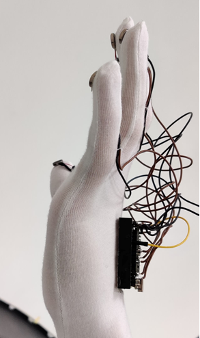
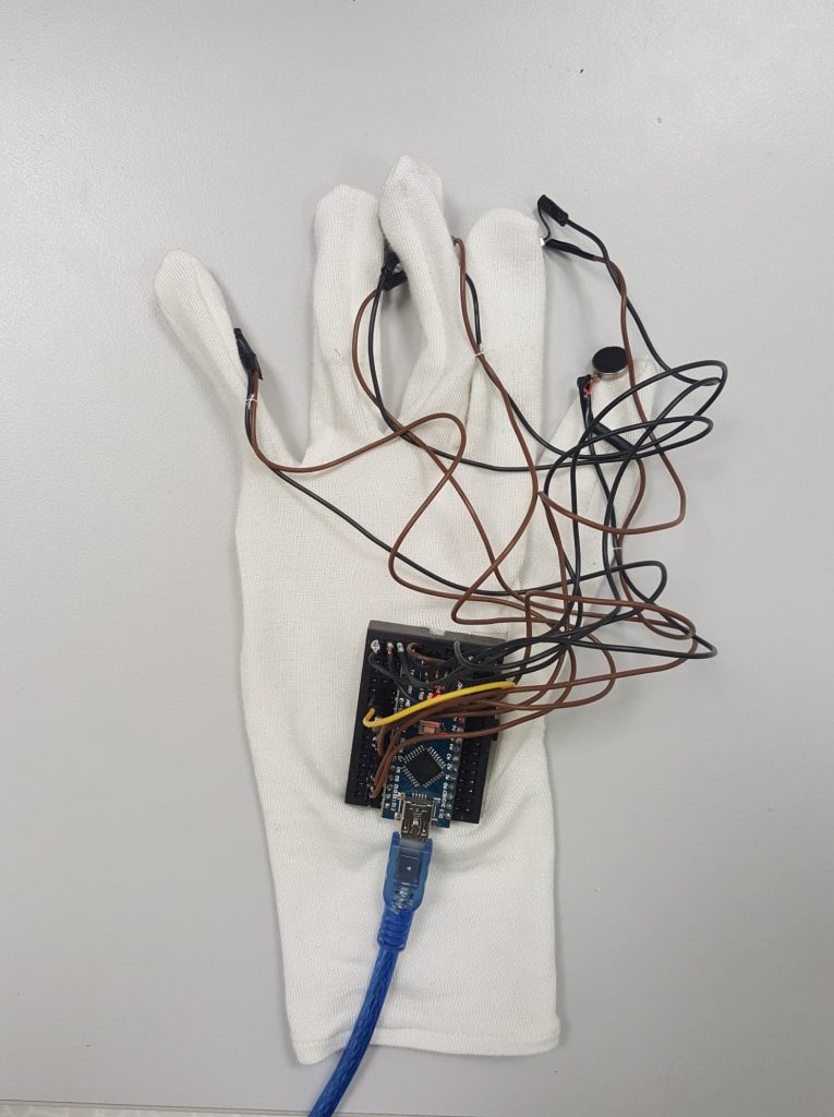
Assembling the gloves, consists of soldering, gluing the parts on, a nudge of sowing, and some tape.
William:
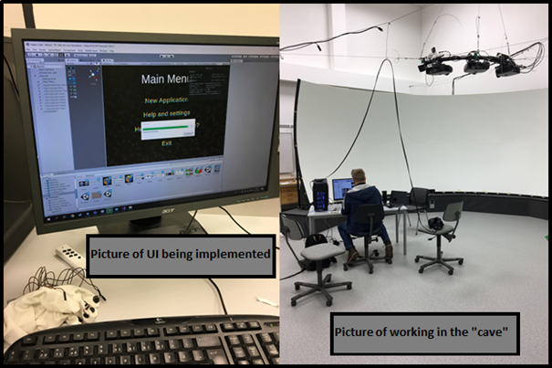
I have been working this last week on implementing the «User Interface» with the «Tutorial» and «Pause Menu» into our main application in Unity at the cave (school). After some issues with text-mesh pro and other assets, the implementation went fine.
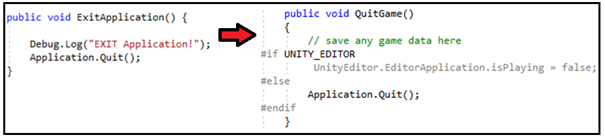
For some reason I had an issue with the Application.Quit(); function not working, when I implemented it into the main application. Meaning when I tried to Exit/Quit the application, nothing happened. I did some modification to the code and then it was working as normal. The issue turned out to be that Application.Quit does not work when you don’t have a “.exe” folder. When you build the scenes in Unity, you need to create a folder where Unity will put the .exe and the other files in. Then you can run it as a standalone program.
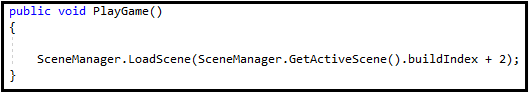
We also added a new scene I named “Load Test Scene”. I had to figure out how we could load the new scene based on how the buildIndex was made (I had to “jump” 2 scenes). I figured out this new code.
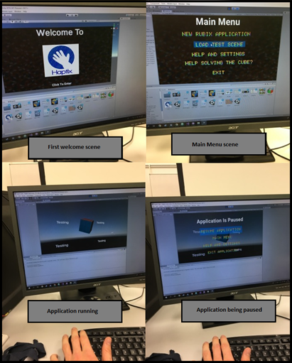
This last figure shows everything FINALLY working as it should.
Daniel:
After having talked to the group and tested a glove. We noticed that the vibrating motors seemed to be quite intense. So we decided that there should be some modifications to how much they vibrate. I believe Tom Erik said that he could look into this on the Arduino side. While I was given the task to do something with this through Unity.
I landed on improving the fingertip.cs script, that by quickly increasing a signal strength variable based on time over impact (a collision). The reason for this was that I wanted to give an illusion of different types of pressure. Since there will be nothing stopping a user from moving his/her hands in real life.
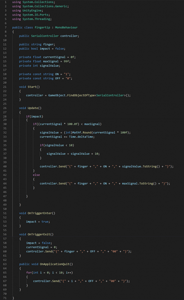
The fingertip script will also send a series of messages to the Arduino, telling it to turn off the vibrating motors when the Unity application is quit. This could also have been extended to sending a series of messages to the Arduino, if the Leap Motion Rig cannot be detected. I.e. if your hands are not visible for the Leap Motion, then nothing should vibrate.
Another update to the fingertip script is the way a message is sent to the Serial Controller (which will then transmit to the Arduino). After some discussions with Herman who is doing the Arduino side of the glovebridge. We decided that it could be useful to change the format of the message.

In this case, the format will consist of a string with 8 bytes on the Unity side. Where the curly brackets “{” and “}” will be the start and the end of the message. The “,” is the delimiter. FingerID will be the finger the message includes (e.g. 8 for left index finger or 9 for left thumb). The on/off signal will be either 0 or 1, where 1 indicates on and 0 off. Lastly, the signalStrength will be a number from 10-99, which can be used to either weaken or enhance the vibration.
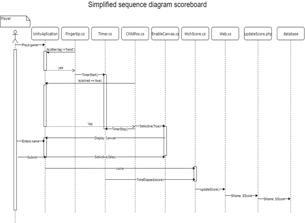
A potential scenario for the bi-directional communication between the Unity application and the gloves can then be:
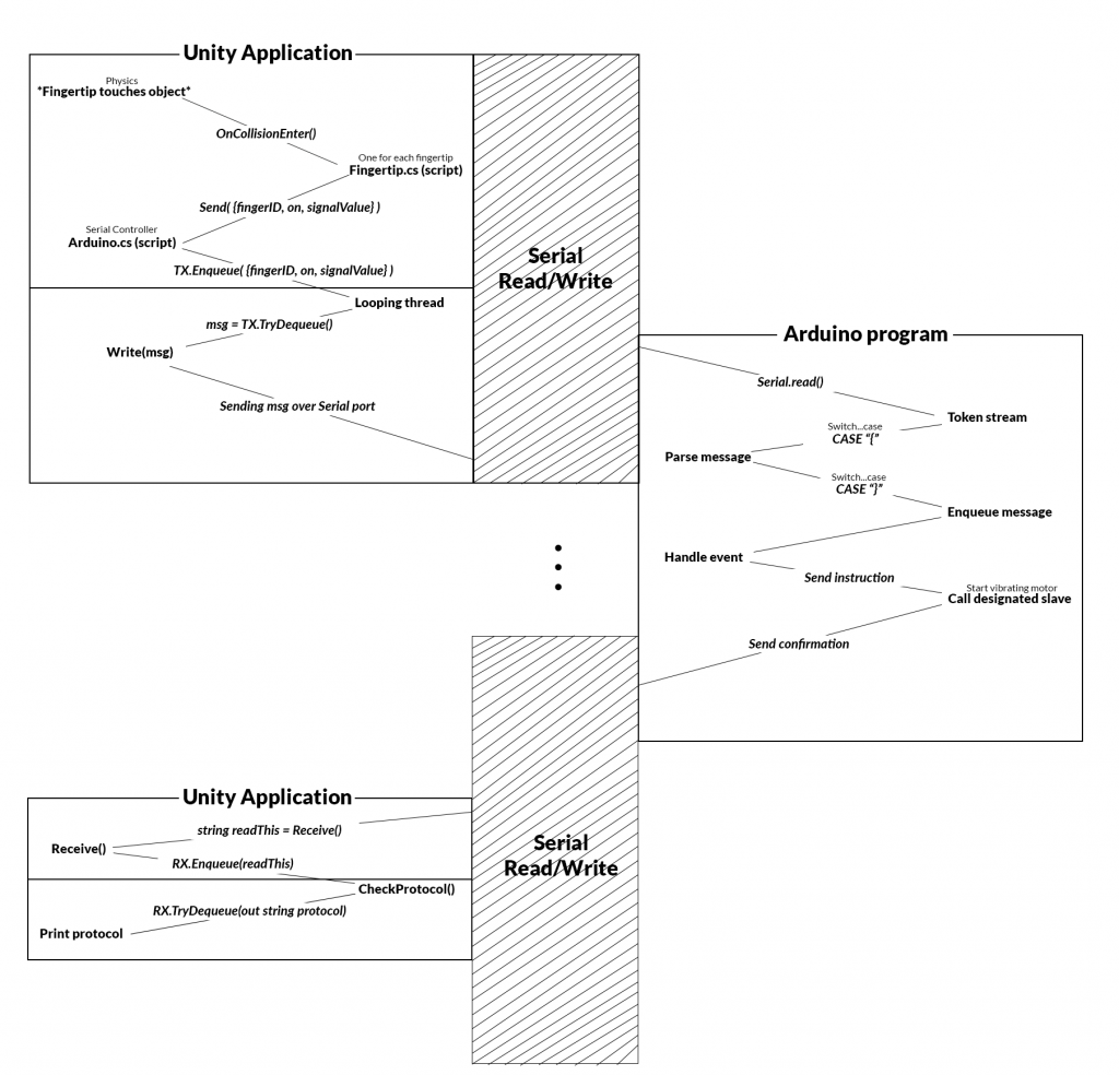
N.B. The diagram above is based on touching an object in Unity. Also, the Serial Controller’s previous name was Arduino.cs.
Furthermore, since we now know the precise format of the message being sent from Unity to the Arduino. I updated the Serial Controller program with another safety mechanism. In this case, the Send() function in the Serial Controller will check if the the message is the correct amount of bytes before enqueueing.
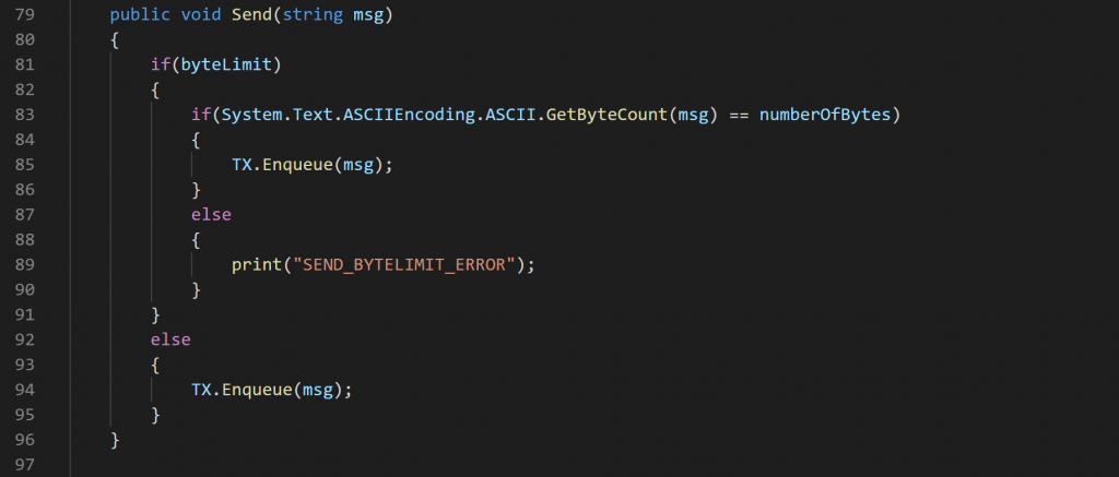
Another thing I could’ve implemented into the Serial Controller script is an error log. Something which could’ve counted potential errors. Though, I saw this as not very important on the stage we were at.
My initial plans for this week was to continue working on the Unity application’s environment. But after the meeting with the group, I decided to rather work on extending the fingertip script. Create an example draft of a Powerpoint we can use (for the presentation) and plan how we can finalize the project with the group.
Another thing that happen this week was that Herman got done with the program for the Arduino part. Where he also suggested some future changes that I agree with. For example, if we were to re-do the project we could save one microcontroller by letting Unity speak directly with the other two over Bluetooth. I.e. instead of having a master/slave setup, we could drop the master and tell Unity to speak to the designated slave.
Another thing we also could have done is to send all the motor states to the microcontroller. Instead of sending one finger at a time. E.g. {0, 99, 69, 42, 0}, which if for the right hand would be {thumb, index, middle, ring, pinky}. The main reason for why we are sending one finger is because of how I have set up the collision system. Something I talked about in week 43 and 44. Not to mention that we could have dropped the section for the on/off in the format. Since the signal strength could have been used for this, e.g. 00 equals off and anything above 10 equals on.
Let me specify further:
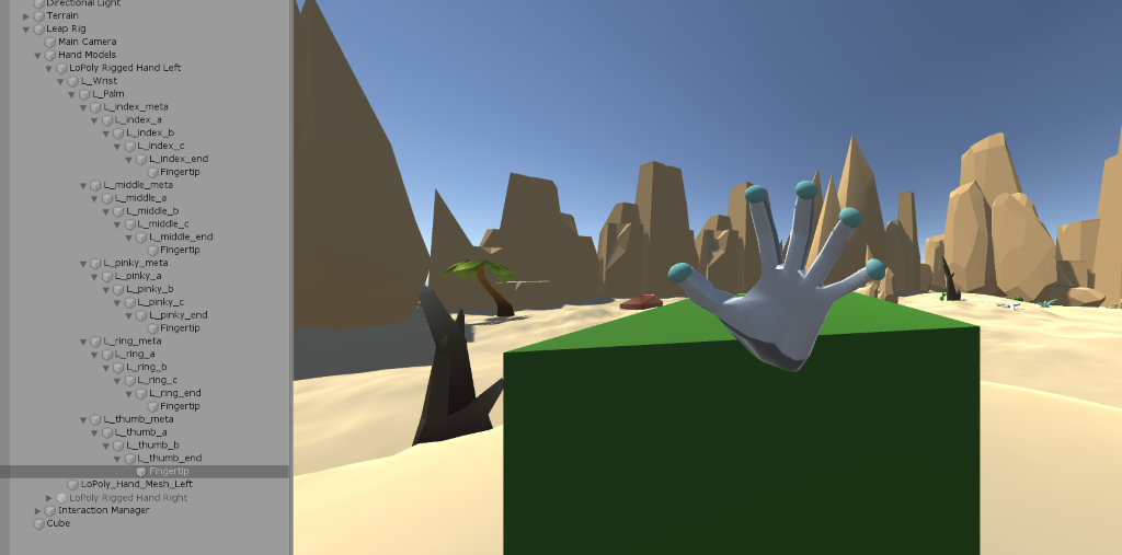
N.B. The scene seen in the picture above is outdated. Scene seen in week 47 is the new.
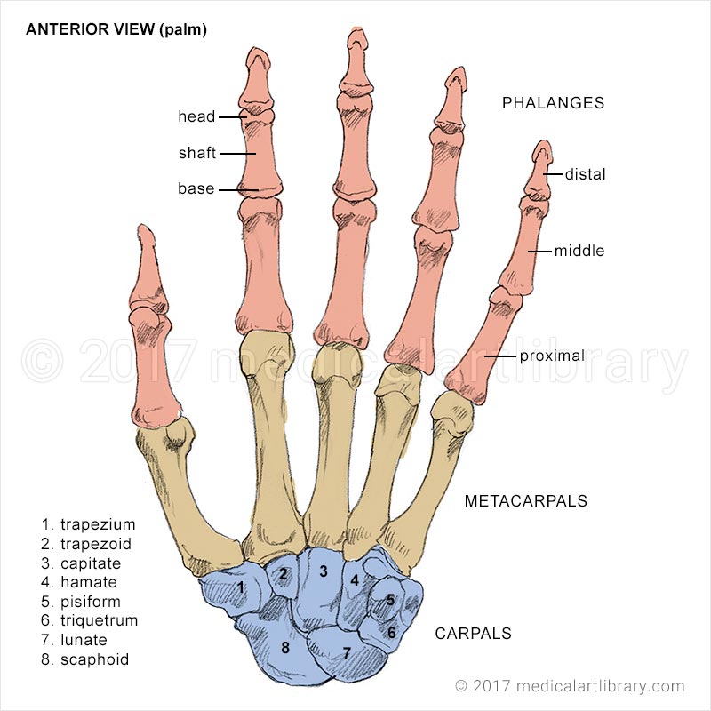
Out from the picture above, it visible that there are a total of 5 sphere colliders on each hand (they are minimized in the final demo). These are responsible for detecting an impact on either OnTriggerEnter() or OnTriggerExit(). But, this could have been extended further. For example, we could have added a collider for each joint in the hand. Which could’ve included the intermediate phalanges, proximal phalanges, metacarpals and carpals. Not just the distal phalanges.
Though, extending the anatomy of the hand would also mean that we would need more electrical components. Which would’ve been ideal, especially if we decided to drop the Leap Motion altogether in order to create our own and complete system.
The esthetics of the glove could also be upgraded. For example, we could’ve 3D printed a container for the microcontroller and incorporated a battery into it. While also making the wires shorter, preferably having them sewn better into the gloves.
But, at least the serial controller and fingertip is complete. The fingertip could’ve been better or extended further. But, the mission here was to establish an asynchronous serial communcation between Unity and Arduino. A full duplex communication through safe parallelism with threads in Unity. I can also mention that the American Old West scene is also complete. The scene has both A and B requirements.
My work has been uploaded to the Github repository that Steven has access to.
Even:
For the smart system course our group decided to make a system where a glove give you haptic feedback. The system is composed of a few different parts. The gloves with motors and Arduino communication. A scene in unity where the simulation would take place. And the communication between unity and the Arduino.
I struggled to find something to bring to the table. I started looking into using AI with reinforcement learning to have a competitor to play against. But due to my lacking knowledge of AI as well as the limited documentation I was not able to make it work. I used a couple of weeks researching ML agents in unity. To solve a Rubix cube is not a straight forward process and to define rewards for the system to works is very hard. During my research nobody have been able to get this to work seamlessly. One other option would be to brute force the cube solving.
I decided to abandon the AI solution and instead find something else to do. I really wanted to see how unity communicated with servers and decided to make an online leaderboard with a “product” website to accompany it.
The Website is hosted locally using WAMP server and the database is phpMyAdmin. To save some time I used a bootstrap template to expedite the process. The biggest reason for using the template is so I would not have to use tens of hours making the website look beautiful using CSS, I was more curious of how I could make unity talk to a database.
How to run website:
To run the website, you need to download wamp server https://sourceforge.net/projects/wampserver/.
Then you have to save the folder Template to the www directory in wamp.
C:\wamp64\www (can differ depending on where you installed it)
After doing that you need to open phpMyAdmin and make a database called “scoreboard”.
After doing this you can import the file scoreboard.sql using the import function in phpMyAdmin
Scoreboard.sql is located in the Template folder
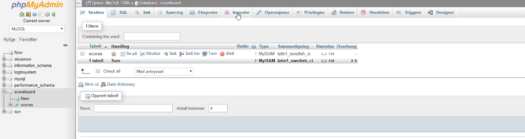
The table will then automatically be created with the right variables.
The Website
To start of I made a basic website with an About page, showing of all the team members and explaining their role in the project.
A contact page where you could contact us using a contact form on the website that would send us an email on our fictional haptix@gmail.com address.
A product side where all the components are described was also made, here I also made a complete description of the system.
A blog site where also made, but instead of re posting everything to our own website I linked to dronesonen instead. This was again done to prevent the tedious project of formatting everything in CSS.
These sites are made by using simple html code and are not difficult only time consuming.
And then to the fun part. The Scoreboard.
To have a scoreboard we first needed to define how the score should be kept. In real life Rubix cube competitions the players are scored by the shortest time, where the solver would have x amount of time to look at the cube before beginning to solve it.
We decided that the most practical way would be to start the timer when the user started touching the cube and stop when the cube is solved.
The whole scoreboard depends on a few different components. In Unity there is 6 different scripts working together. Two of them are mainly written by (X) but I added my own functions to the script to enable the scoreboard. The rest is written by me
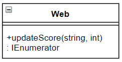
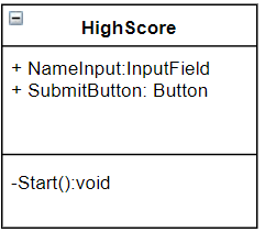
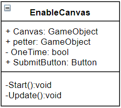
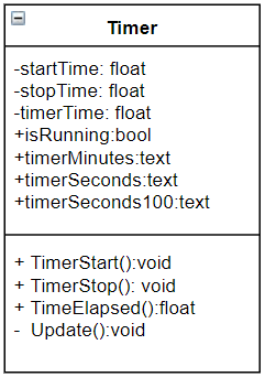
Fingertip.cs(Daniel), Timer.cs, ChildPos.cs(Petter), EnableCanvas.cs, HighScore.cs and Web.cs
Timer, EnableCanvas, HighScore and Web are connected to an empty game object in unity that is used as a manager. Fingertips are used on every fingertip on the hand model, and ChildPos is on the cube it self.
Then there is a couple of canvases to show the live timer, and a canvas to take a name as input after completion.
There is also a couple of php scripts to be able to store and download data from the database.
Fingerip.cs:
The fingertip script is used to see if the colliders of the hand model touches anything but them selves, meaning the cube. I use this function to start the timer.

We had to make sure the timer would not start before the cube is scrambled. To be sure we only started the timer when the cube was not solved (cube is solved from the start of the game, then gets scrambled). This calls a function in the Timer.cs script TimerStart();
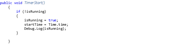
isRunning = false; when the game starts.
This bool is to ensure you can not start the function while its already running. We then store the global time of unity (Time.Time) to a variable. The debug is for prototyping only.
Then Petter made a function in ChildPos.cs to check if the cube is solved. He does this by checking if every cube is back to the place they were before scrambling. When this is true the bool Solved = true; He then calls my function TimerStop() which is located in the Timer script.
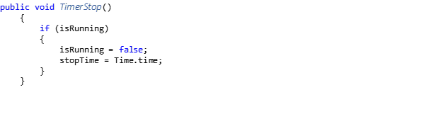
TimerStop does the same thing as timer start except storing the time of completion to a variable.
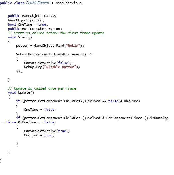
When solved switches from false to true, a script called EnableCanvas activates the canvas where the player inputs their name.
This process turned out to be a bit tricky. We could not simply activate the canvas when solved = true. This is because the cube is solved when you start the game. To ensure the canvas didn’t pop up at the beginning of the game we had to make a sort of timer to check if the cube had been scrambled then we could activate the canvas when solved = true. We also wanted the canvas to disappear when the user pressed the submit button. We therefore set OneTime = true to exit the function enabling the canvas to be deactivated again. When the user pressed the Submit button a few things happened.

The HighScore scripts takes over and sends the name that the user inputs, as well as the return value of TimeElapsed which is a function in Timer script that calculates the time passed, using updateScore().
updateScore does this by using the Unity Networking functions. The script called Web, which updateScore is stored in, oversees handling the network traffic. This uses a UnityWebRequest.Post to send a data to a server via HTTP POST.
One of the problems we encountered is that the form functions in unity were not able to send floats. Floats would be optimal for us to store time due to the increased accuracy compared to int. We had to round to nearest int instead loosing some accuracy but making sure we got the system to work.
After the updateScore has sent the information we move over to the sever side of the scoreboard. A script stored on the server called updateScore.php connects to the database and takes the two variables name and score and store them in their respective coulomb’s in the score table.

When someone wats to look at the scoreboard a script stored on the server called leaderboard.php steps in. This script reads everything from the table in the database and sort them in ascending order to ensure the lowest time is placed highest.
//see full code in the repo
$sql = “SELECT name, score FROM scores ORDER BY score ASC”;
The Update funtion in Timer.cs is just to show the live time.
Class Diagrams: