Mechanical
This week has gone to further assemble the air hockey system, and we now have all the components except the timed band, which will arrive either this Friday or Monday. There has been a lot of complications with shipping, but we are fairly certain it will arrive at this time since we have had direct communications with the salesman, and it is shipped from Sandnes, Norway.
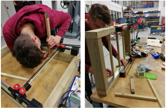
We have also cut out the plexi-plate for the air hockey board top plate. This was a very time-consuming process, but it finished just in time for me [Markus] leaving for the rest of the week. Furthermore, we finished the bottom plate for the fan construction. As of now, we only have one fan, but hopefully the others will arrive very soon. This is not a critical component, but it would be nice to have it now rather than later.
Most of the construction has been a cooperative process with the electrical students, so a lot of the pictures will come in their section as well.
There has not been much 3D modelling this time around, but we will soon start to make some 2D drawings of the system, exploded views, etc. so that everything is more presentable at the end of the project period.
Electro
This week we have been helping with mounting and implementing the mechanical components to the board, so that we could fit the plexiglass plate into the board. The bridge is now attached to the board, so we are able to start testing the camera on the actual board.
We wrote a program for calibration of the stick. It is very important to do this before every game, so the computer knows where it’s holding the stick and so it’s able to play against someone. Calibration works like this: When the stick is moving towards the side a button is pressed and coordinates are set to zero. After that we must measure very precisely the exact steps of the stepper motor, how many steps it must do to come to the other side across and forward. That way we will get the coordinate system for our stick and we will be able to send its coordinates to the Arduino so that we can move the stick to that exact location.
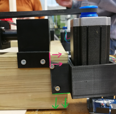
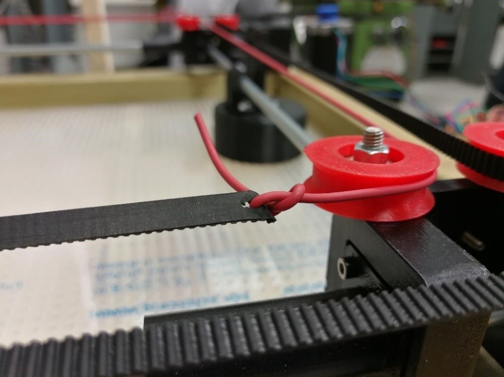
Theory doesn’t always cooperate with practical work. As it is seen on the picture below, we had some issues with calculation with mounting the printed parts on the wooden blocks, but we are all learning from mistakes, aren’t we?
We are still having trouble with the shipping of our components, such as the band, fans and LED strip. The shipping company mixed the addresses and sent it to the wrong location, and we are now expecting these to arrive next week. Despite all these problems we had to start testing the prototype; this is the result of engineering improvisation.
Computer
This week the computer engineering students have been researching how to progress with the next step of our program (implementing rudimentary defense), fixing a couple of bugs in the program, and making some of the information more human readable for testing purposes.
For the program, we have discussed how to best implement the computer’s defensive capabilities, the very rough sketches of which is shown in the image below. Two ideas are displayed here: the first is the bottom rightmost tiny circle. Initially we thought we could perhaps simply calculate the vector between the puck’s position (of which we already have an array), and a static point set in the middle of the goal, and have the stick intercept this vector. We realized after some discussion that this would not suffice, as this would only work if the puck was always aimed at the middle of the goal, which would not always be the case.
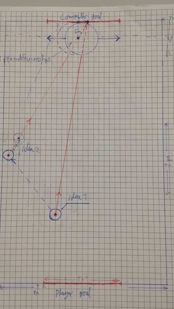
Consequently, we advanced to our second idea, which was to calculate the trajectory of the puck based on its previous position, and its current position, by constructing a vector out of those two positions, but we weren’t quite sure where to go from there. Steven suggested that we construct this vector, and check where said vector intersects with the X-axis (aka where Y = 0), and if it intersects in the boundaries we define to be the goal, we have the stick intersect this vector, thereby defending the goal. To accomplish this, we make use of a couple of simple formulas:
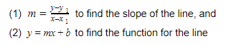
Now, to find where this line intersects with the x-axis, we need to solve equation (2) for x where y = 0:

This is the x-coordinate where our line intersects with the x-axis. Using this coordinate, we can check if it lies within the boundary we define to be the goal, so:
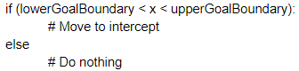
We will need to implement this math into the context of our program, and subsequently test if this gives us the correct values. To test it, we will first calculate some points by hand, and see if the program outputs the same results as we get on paper.
As for the bug fixing, we have been able to locate and fix the issue where our program would crash if it was unable to find a contour in the initial frame, or if the contour ever went offscreen. The reason for this was that we would be checking for non-existent indexes in our centroid array, and it was fixed with a few simple “if” checks at the locations in our program that used the array in question, to ensure that the array had a sufficient amount of elements.
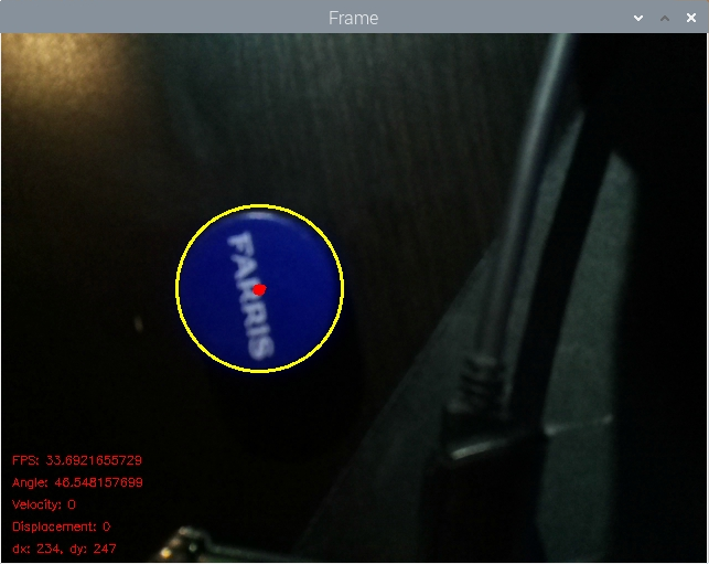
Finally, the smallest (but most visual) change this week was making the program more human-readable; we now output all of the information generated by our program directly onto the frame, making it far easier to discern the numbers, as opposed to reading them directly from the terminal (where they fly by extremely fast).