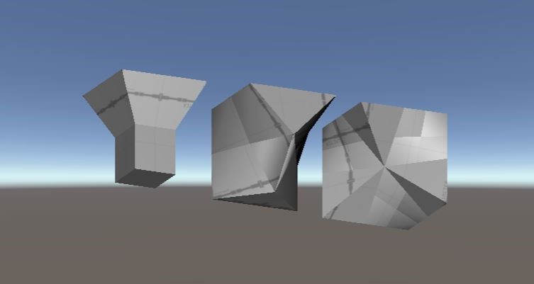
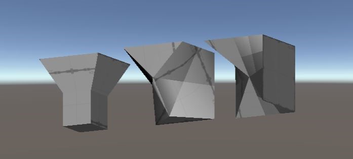
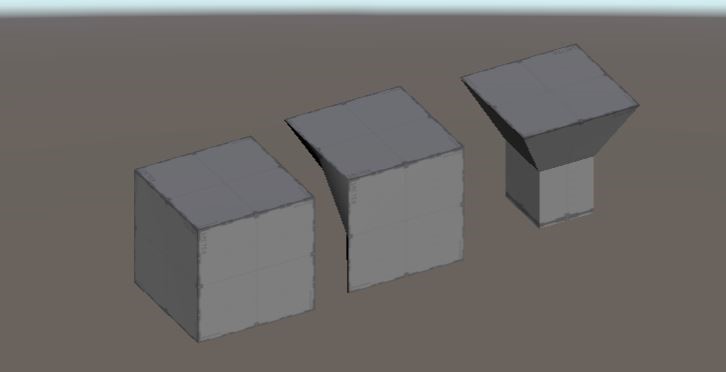
Petter
Created some custom cube designs and discussed implementation of how our Rubix cube reacts to virtual touch.
Daniel
I had to rework most of what I did for the previous weeks. Rather than using Leap Motion’s properties and methods, I created my own fingertips using a custom script and sphere 3D objects.
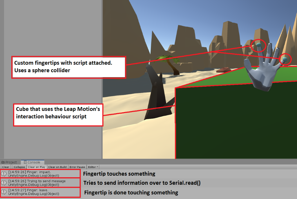
The image above illustrates the current state of the Unity application. When there’s an impact on any of the fingertips, a function in a script called Arduino.cs will be called.
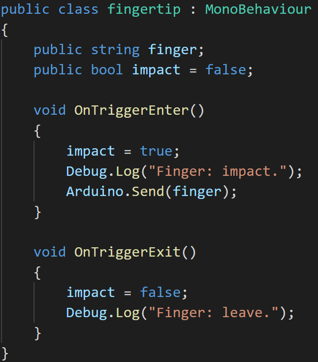
Which will then send a signal to the actual Arduino. Where the Arduino will use serial.read() to get the signal. That way it can handle the slaves and vibrating motors.
A little side note, the fingertip script seen here aren’t necessarily fully complete. I am currently working on bi-directional communication between the Arduino and Unity application.
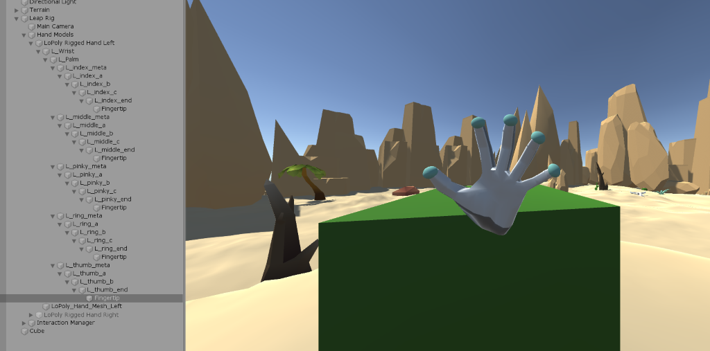
The image above illustrates the full hierarchy of a hand, in this case the left hand. Once any or more of the turquoise touches something, a vibrating motor for the respective hand and finger should start. The green cube seen in the image is just a placeholder for the interaction Petter is working on.
William
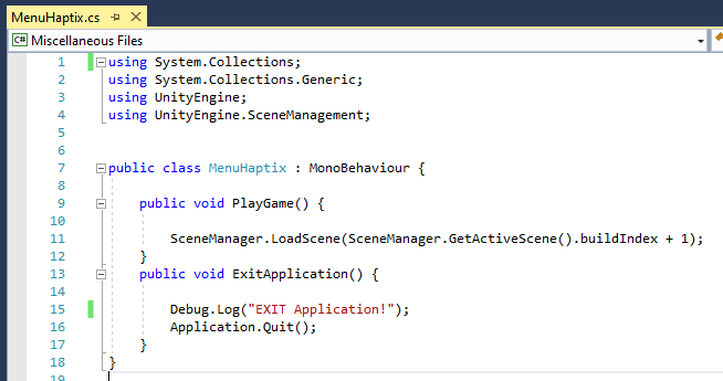
I am now done with the User Interface for our application (there will be small changes/adjustments). The UI is of course made in Unity, and I have added some implementations and functionalities using C# as you can see in the GIF.
Short link: https://gph.is/g/Z5nYrxO
Link: https://media.giphy.com/media/f4aAw5Mrg42apNSL8N/giphy.gif
HTML5 video: https://giphy.com/gifs/f4aAw5Mrg42apNSL8N/html5
Herman
The two last has been more focused on other classes and I therefore haven’t done as much as I probably should. I have still managed to start further code communication in the gloves, where I have spoken with Daniel about how he wants the information in and out of unity. This, for my part, was a simple Serial.read and Serial.print, but we still need to have a united understanding of how they will communicate. In this case each finger, on one hand, is assigned a value between 1-5 where each hand is represented as either a negative or a positive value. After this is up to me to make sure that the right information reaches the right unit. This as simple as saying every value between 5 and 1 is unit 1 and -5 and -1 is unit 2, and then build it from there.
There is also been made a rough layout of the sensor reading code so that when in week 45 I can easily continue the work with putting meat on the bone. As well as this I have soldered the IMU and done a rough test to see if it works and start to figure out which values from the IMU that are needed for this project.
When all this are done, we are going to start testing and error detecting the system.
Tom Erik
The flex sensor signals, require an amplification, to increase the span of sensory points. The micro controllers allows for 8bit sensitivity, currently only about 350 are being utilized. We consider using an operational amplifier for the amplification. Thought setting it up would be smooth sailing, turns out it wasn’t has spent some time figuring the circuitry out.
Some other sensory testing has also been done.