Mechanical
This week has not yielded much progress, as the 3D-printers have been occupied a lot of the time and we need all the parts before we begin mounting them together. Therefore, rather than not doing anything, the parts we’ve had available have been mounted together and they have gone through a kind of test to see that everything fits together as sub-assemblies.
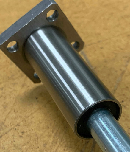
One of the problems we encountered this week is with the linear bearings that we meant to use to move the system along the length of the air hockey table. These bearings were said to fit 10 mm diameter pipes, but for some reason they were way too tight. We soon found out that even though it said 10 mm linear bearings they were actually made for 9.8 mm pipes, which the ones we have are not. Therefore, since time is of the essence we decided to model and print our own bearings and use them instead.
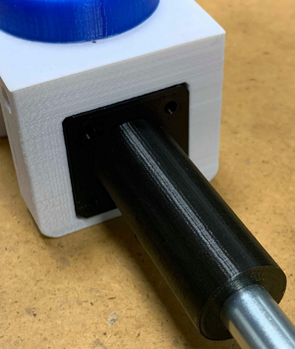
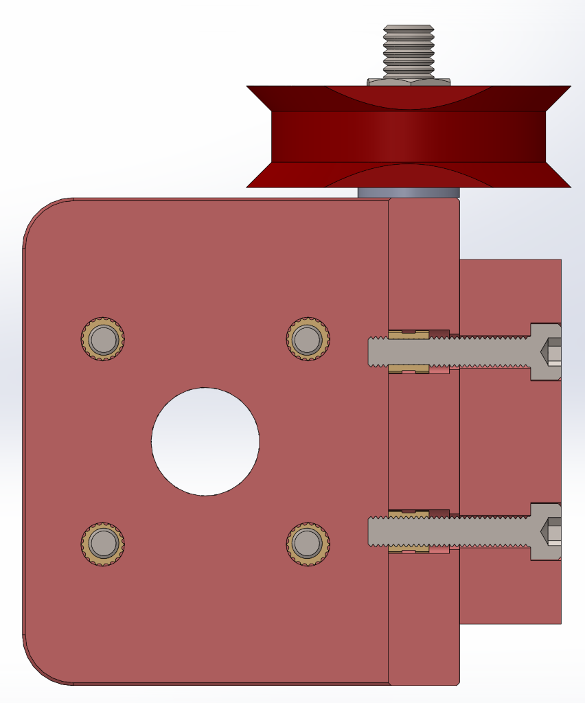
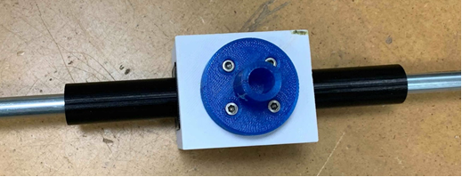
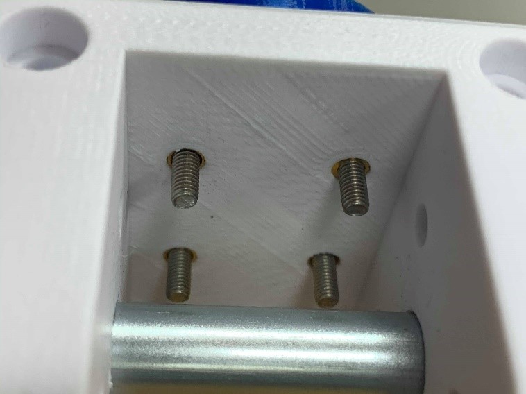
One of the parts we are finished printing and have assembled is the center mount which is meant to move the stick back and forward on the air hockey table. The bolts are connected through the parts using knurled head nuts as shown in the SolidWorks model bellow.
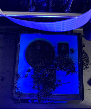
The plan this week was to finish all the parts and start assembling everything together today. This was also looking to happen as of yesterday evening when the last print was set to go over night and be finished in the morning. A last checkup was done two hours into the print and everything looked fine. Unfortunately, somewhere during the night the print failed drastically, and the result can be seen in the below image. Consequently, we were forced to do the prints during the day today and the mounting process had to wait since these were critical parts for the whole system.
As of tomorrow when all of the critical parts are finished and ready to assemble, we will prioritize assembling everything and start testing that the components from mechanical, computer and electrical work together and optimize the system further.
Electrical
This week we’ve been improving our program for the interface for the Liquid Crystal LED screen. You will be able to choose between different game modes to play against the »unbeatable« air hockey machine. For now there are going to be two different game modes. The first one is to play as long as the score reaches some point, and the second one is going to be the time mode, were you play for a given duration (e.g. 2 minutes). Later on, should we find the time, we will try to add more game modes, to make the game experience even more interesting.
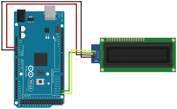
(Source: Fritzing.org)
We’ve also been working on programming the stepper motor movement for Arduino MEGA. We’re not sure what kind of problems will come when we connect the Raspberry Pi 4 (which is tracking the disc all the time and calculating the vector of its trajectory) and establish communication between these two different pieces of hardware. This will be a task for next week, where electro and computer will work together to make the serial communication between the Arduino and the Raspberry Pi.
We have also discussed with the computer engineering students to determine the behavior of the computer opponent, namely when it should defend, and when it should attack, and how we should use the information from the raspberry pi to enable the computer to make this decision. For now, however, we have decided that we will first focus on making the computer capable of defense only, and handle attack at a later stage, as this will present a few more complications.
Finally, we have also been doing some research about the functioning of the encoders. These are electro-mechanical devices capable of converting the angular position or motion of a shaft or axle to analog or digital output signals. Concretely, we have been working with one able to convert the angular motion to some digital pulses. Using Arduino we are able to process the information generated by the encoder to calculate the exact position of the stick in the game field.

(Source: Wikimedia.org)

(Source: Wikimedia.org)
The signals A and B generated by the encoder gives the system the ability to calculate the speed, direction and angle rotated of the system attached to the encoder.

Computer
This week the computer engineering students haven’t made too much progress with the program, and so it’s mostly in the same state it was last week. Some more research has been conducted to determine if there were any suitable alternatives to our method for finding the contour and subsequent centroid, at Steven’s request, but we were unable to find anything concrete and modern; a majority of the projects we found on the internet appear to employ the same method we currently use. Consequently, we have decided to move forward with the way we do it now, and be satisfied that we were able to cut a number of unnecessary algorithms from the program last week. Furthermore, it was insightful having to re-analyze which parts of our program was truly necessary, and which could be cut, which was valuable in of itself.
Other than that, we have been impaired as a result of having to wait for the various parts we have ordered to arrive, as well as the 3D printer failing its latest print, as mentioned earlier. We’re unable to start integrating properly and begin testing how most of the subsystems work together. Therefore, we have spent some time preparing for when we can begin integration, by considering things that could wrong, and begin work on various administrative tasks (such as giving our requirements and test cases another look-over, as well as adding a new test case result table) so that when we have all our parts, we can start immediately putting them together, connecting interfaces, and so on.
Next week, our plan is as follows:
- Perform the same performance tests on the Raspberry Pi 4 as we did on RP3.
- Consolidate the results from these performance tests to visualize the difference.
- Consider the Arduino to Raspberry Pi 4 interface (serial); connect and code it to make it work, so it’s ready to go when we have the parts.
- Consider how best to adapt our program to the integration; coordinate system must fit the board perfectly, must define goal coordinates, etc.