Mechanical
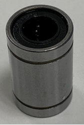
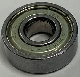
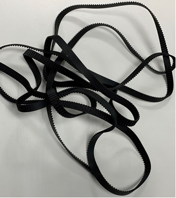
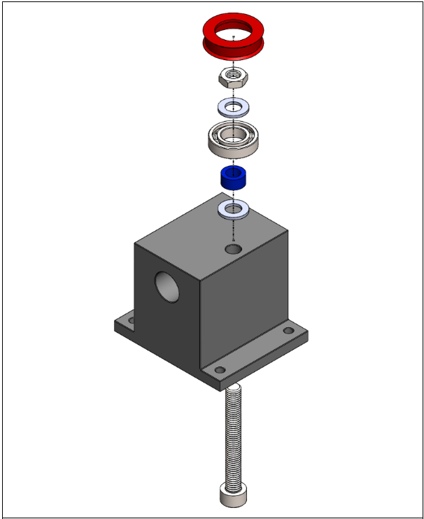
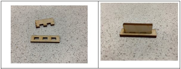
This week we have finally got some of the parts that we ordered earlier, so now we can control all the measurements and make a more detailed model in solid works and make test parts and find all the parameters that make them fit with each other. The following parts have arrived this week:
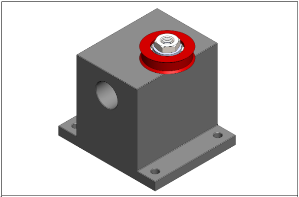
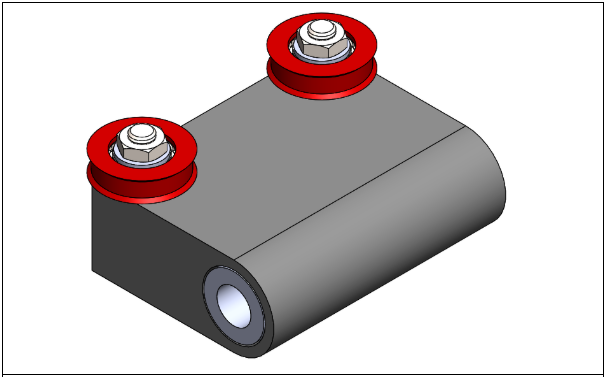
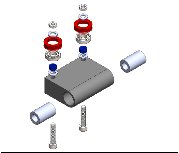
As mentioned, the designs are now made to be more detailed and similar to the equipment that we have. All parts are also made more systematic so it’s easier to work with continuously from day to day. As of now the following parts, sub-assemblies and assemblies are more or less finished in design. Some further “print testing” needs to be done to see that everything fits after the contraction and expansion of the plastic that is caused from the 3D-printing process.
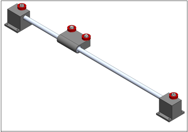
For those who have read all our blogs you can see that there has been a major design change in the case of details. This, alongside with continues printing and testing, will occupy most of the work that is going to be done the next few weeks.
As for the building part we have created the first prototype for the “bridge” so that the computer group can use it for testing with the camera. Unfortunately, some the measurements we got was not correct, so a few moderations have been made after the prototype was first finished. Following you can see some action pictures of the making of the bridge.
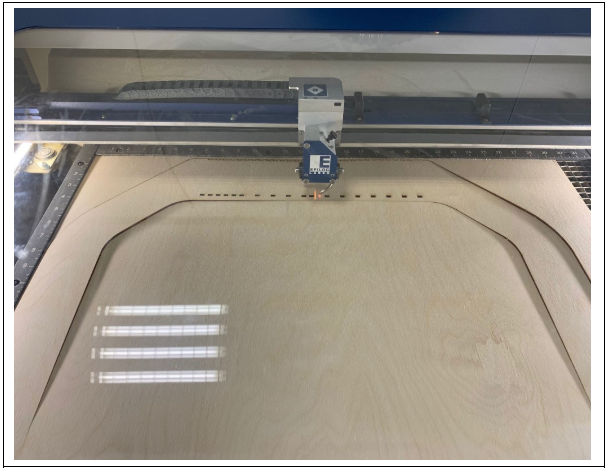
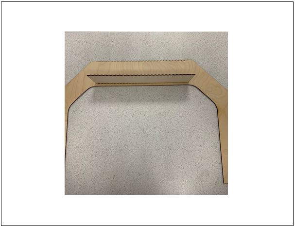
The final product will be shown in the next blog.
Electrical
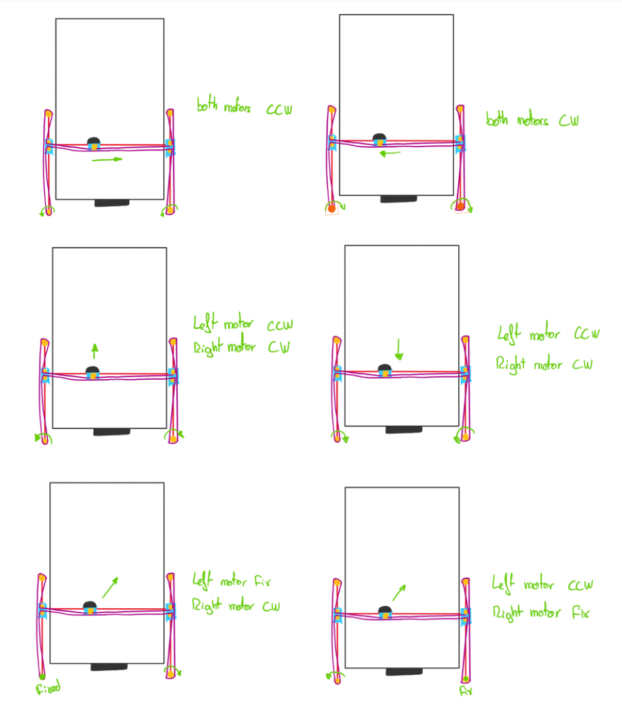
This week the electronic department has been working on the kinetic model of the motors, the basics of its movement will be explained below.
The movement of the stick is generated thanks to the combination of movement of both motors implemented in the prototype; this means it’s necessary to control both motors independently at the same time to be able to generate both simple and complex movement.
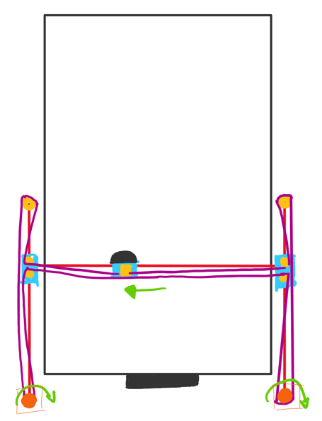
For example, to move the stick to the left, it’s necessary to rotate both motors in CW direction at the same speed.
Some of the simple movements that the computer is able to perform are represented in the illustration below.
Computer
Once again, we have decided to divide our resources. At this point in time, we have been able to install everything that we needed on the new Raspberry Pi 4, but we have now run into an issue wherein the CPU overheats, which we discovered was not an uncommon problem for this version of the Pi. Consequently, while one of us works on solving this problem, the other has continued the development of the program itself, as well as addressing some other interdisciplinary tasks.
As for the program and interdisciplinary tasks, as planned, not much progress has been made on the program itself; at this point, it more or less does what it needs to, and we need to wait for the other aspects of the project to progress before we can start testing it properly. That being said, some more testing has been done in an effort to determine whether the velocity calculation works correctly, and as far as we can tell, it does, but as last week, it is very difficult to tell, as it’s calculated in pixels per second. It is likely that we will discover whether it works correctly once we start testing it with the board itself and see if the computer acts correctly in relation to the information it receives.
The interdisciplinary tasks we needed to work on was:
- A block diagram of the system, showing our subsystems and explicitly defining our interfaces. This should have been done far earlier in the project, incidentally.
- Organize our system requirements and create test cases to ensure (at least) our A system requirements are somehow tested.
The following diagram is the block diagram of our system:
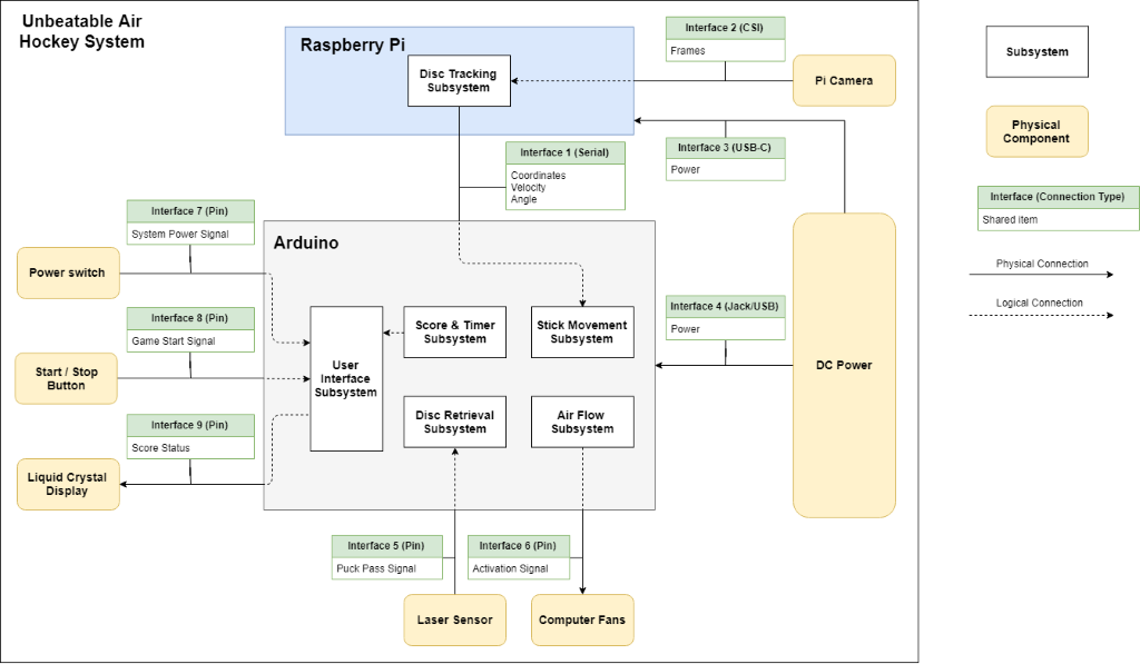
In this manner we are able to neatly and concisely define each of our interfaces, including what sort of interface it is (e.g. USB, pin, serial), and what information is shared across that interface (power, signals, etc).
We organized our system requirements in a spreadsheet, numbering them and defining their priority (A, B, or C), as well as what test cases verifies it. Below follows an excerpt of this spreadsheet, showing an A, B, and C requirement respectively:


The priorities are color-coded to easily distinguish the importance of the requirements: light blue being A, grey being B, and light orange being C. This color-coding persists in the test case spreadsheet:


As for the performance issues, the Raspberry Pi 4 is undeniably more powerful than the old RP 3, but the power comes with the cost. The new Pi generates considerably more heat than all the previous boards. The heat is something that we first detected when compiling the OpenCV library on our newly purchased board. The suspicion of overheating was confirmed as a fact after researching the issue. Sustained load bringing the board to its thermal throttle point – the temperature at which the system-on-chip (SoC) reduces its performance to protect itself.
The Raspberry Pi foundation is well aware of the problem and released a firmware update for the VLI VL805 USB controller as a partial solution which we decided to try. The firmware update improves the temperature conditions, but it alone does not prevent the Pi from throttling under sustained load:
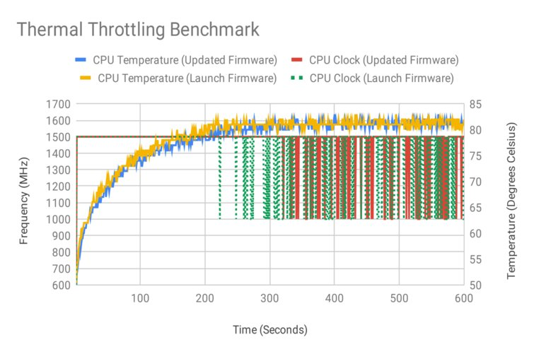
(You can read more about testing RP 4 with the firmware update and Thermal Throttling Benchmark explained in detail here [1]).
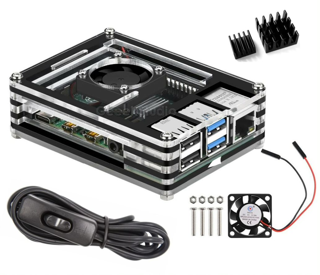
In order to keep the Pi from throttling we had to invest in a cooling system. Luckily, we found a cooling kit at eBay for a reasonable price with immediate dispatch from UK and very short delivery time.
All of that being said, Steven paid us a visit this Thursday (10.10.2019) to further help us with the performance issues. After an insightful meeting, it was revealed to us that we were using far more complex techniques than necessary to facilitate our color tracking and made several suggestions on where we could simplify in order to improve the performance. Moving forward, implementing these improvements will be the primary focus of the software development, and hopefully we will be able to show some of them on the blog by next week.
[1] https://www.tomshardware.com/news/raspberry-pi-4-firmware-update-tested,39791.html