Mechanical
This week has been characterized by a bit of waiting for the teachers to either accept or deny our budget. Luckily, as of 18.09.19 the budget was approved and we will start building the frame and stick system this coming week.
The budget was reworked a bit since last blog post, so here is the updated version:
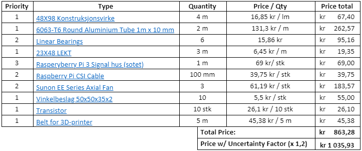
The uncertainty factor was added since the prices may vary from shop to shop and we need to be able to buy some of the equipment from local shops, some of which doesn’t have the best online services.
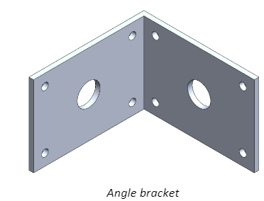
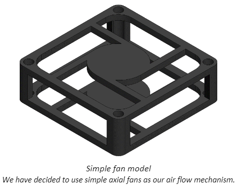
Other than managing the budget some changes has been implemented to the 3D model of the system. Since we are at a point where we need to start testing each of the components and see their fit the changes to the already created components are minimal, therefore we feel there is no need to show them again this week. Nevertheless, some new components have been modeled and implemented. First, some pictures of the whole system as it is now:
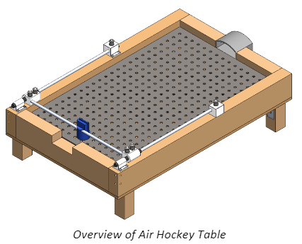
The components for the stick system have been optimized so that they hopefully will fit when they are connected by the timed band.
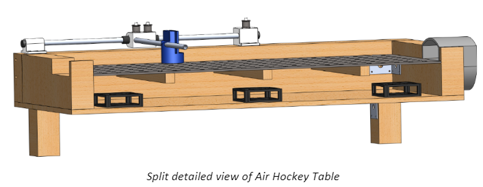
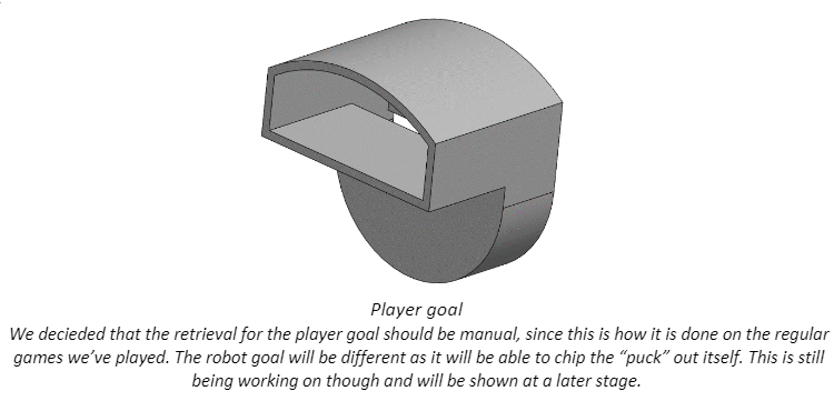
Here you can see the new components that have been implemented to the modeled as it is now, there is more coming at a later stage. These components are to make the model more detailed and realistic.
Electrical
This week the electronic department has continued with the work to control the motors. We started investigating how the micro steps work in physical terms. Also, to be able to understand at all, we need to be sure how our steppers motors works.
Stepper motors
As their name says, the stepper motors move in discreet steps. If we take a look of the angle of each step we can easily calculate how many steps we need to make an entire revolution (360° / 90° per step = 4 steps per revolution or 360° /1.8° per step = 200 steps per revolution). These ones are usually constructed with an outer stator and an inner rotor. In general, the design of the rotor depends on the type of stepper motor that we are using, but the stator is similar between the various types of stepper motors which usually are constructed by uniform teeth around its perimeter, as much as the number of poles (which are simply magnetic sections of the stator, and each one has a winding connected to the opposite pole on the stator; those are magnetized with the opposite polarity when current is applied to the coils).
We’ve found that there are different types of stepper motors. There are three general stepper motor designs: variable reluctance, permanent magnet and hybrid. Instead of the different constructions the stepper motors have a lot of characteristics in common:
- High torque at low speeds (max in stationary position of the rotor).
- Speed easily controlled with frequency of the input pulses.
- Noncumulative positioning error
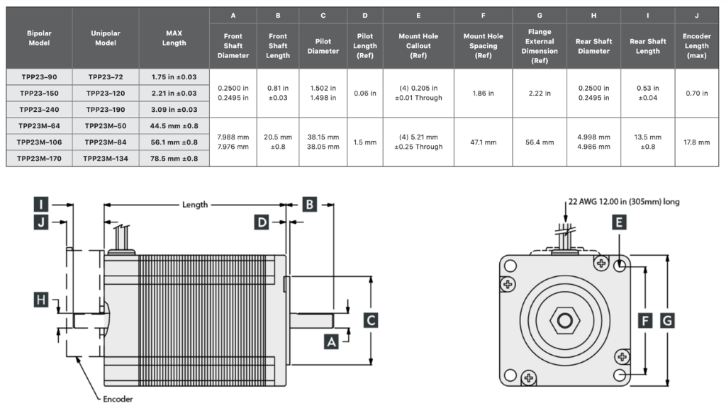
In our case we are working with hybrid stepper motors. These take features from both of the other designs (variable reluctance and permanent magnet), using a permanent magnet rotor (from the permanent magnet ones) with iron teeth (from the variable reluctance ones).
The rotor is typically made of two parts, with one magnetized N and the other S. The teeth of each rotor section are ½ tooth pitch rotated so if the section has 10 teeth, the rotor will have 20.
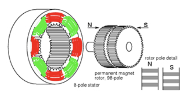
In our motor we get 200 steps per revolution, giving the hybrid motor a small step angle = 1,8º. Hybrid stepper motors also have higher torque capabilities and more holding and detent torque than other designs which make that motor a good choose for our design.
The steppers motors are commonly used in open loop control because they have good precision, and by counting the number of steps you can easily control your desired angle of rotation. Also, they can be used with a close loop control by adding an encoder.
Microsteps
Stepper motors move in discrete steps. For example, our motor which has a 1.8-degree step angle will make 200 steps for every full rotation. This discrete motion has a slower rotation, which makes it less smooth. One trick used to solve that problem at slow speeds is to reduce the size of the motor’s steps. This is where micro steps come in.
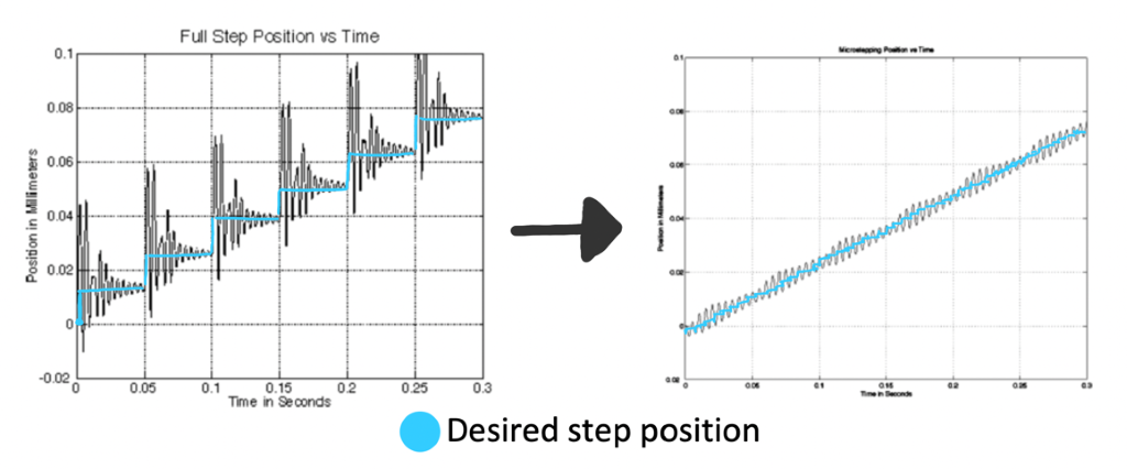
Micro stepping control divides step into smaller steps. For example, if we divide one step 256 times one step will get a step angle of 0.007 degrees (1.8 ÷ 256), or 51,200 microsteps per revolution.
When we are using the microsteps we need to keep in mind that we aren’t playing all the current that coils needs all time, when we are between two steps the incremental torque produced with each microstep is defined by the following equation: TINC= THFS⋅sin(90SDR)
Where:
TINC = incremental torque produced with each microstep
THFS = holding torque (full-step operation)
SDR = step division ratio (number of microsteps per full step)
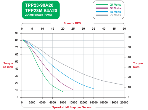
Also, as we can see in the next figure that we lose torque as we increase the speed of the motor, this is something we need to keep in mind to get the system to work properly.
To facilitate the microsteps we need to configure our motor driver correctly. In our case our TB6600 has some switches to configure the different micro steps. These configurations give us the possibility to choose how many micro steps we want for each step. In the next images we can see the switches and the needed configuration to reach the different modes.

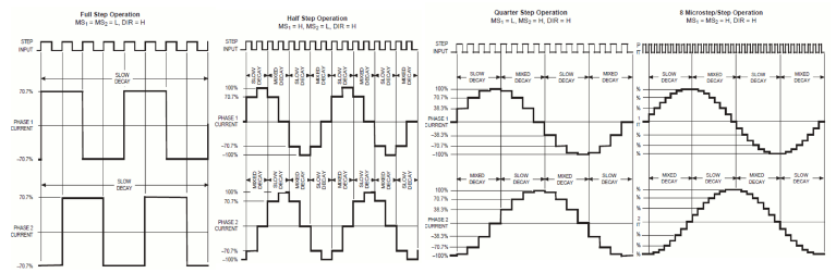
In the next images we can view the diagrams of the current in each coil of the motor in the different cases of micro stepping modes (Full step, half step, quarter step and also 8 microsteps/step).
As we can see, the more micro steps we get, the form of the current in the coils is more similar to a sinusoid. And that make the motor move smother.
Controlling two stepper motors independently with the same controller
To reach all the positions of our game space we need to combine the movements of the two motors, so we need to make the software able to move both motors independently at the same time.
To reach that objective we designed a simple algorithm able to send the step signal to the motors without stopping the hall processes.
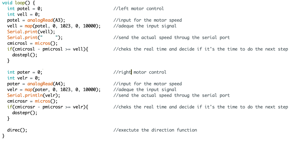
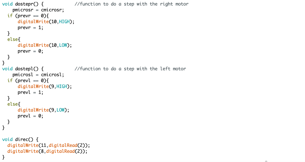
With this algorithm we found some limitations regarding the speed that we can get with both motors, but it’s a good start for the initial design.

Computer
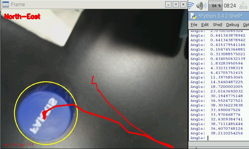
This week the computer engineering students have made steady progress, albeit at a slightly slower pace than before. Whereas before we had a clean, modern, and detailed tutorial to follow on how to begin implementing OpenCV, this is not the case for the more specific things we need, such as how to calculate the angle, velocity, and so on. Consequently, we have had to rely entirely on our own knowledge and experimentation (and vague, mostly outdated advice from the internet). This turned out to be a good thing, as it only deepened our understanding of our progress thus far, allowing us to optimize, segment and abstract the code for improved readability and modularity (i.e. splitting parts of the code into functions).
Now, to implement a new feature (such as angle or velocity calculation), we can simply create a new function for this, rather than attempt to squeeze it into some existing part of the code. In the case of angle calculation, we have successfully managed to implement this, by defining a static coordinate system, constructing a vector from the X and Y components of the object, and calculating the cosine of the triangle formed between the vector from origin to the object (the hypotenuse), and the x-axis (adjacent). This gives us the preliminary means of determining where the arm will need to go to match the incoming puck in order to put up a successful defense.
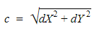
To elaborate, it would look like this:
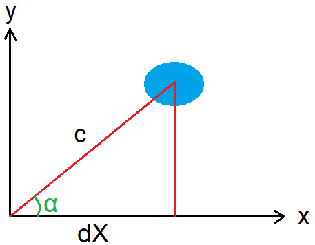
The coordinates of the object at any given time is denoted by dX and dY. Out of these, we construct the vector that will form the hypotenuse (c) of the triangle:
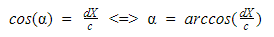
Then, by using the object’s horizontal position dX as the adjacent side, and the vector formed between the origin and the object as the hypotenuse c, we can get the angle by using the cosine of the triangle formed by these:
The biggest issue we’re facing from the software side of things, however, is the fact that our version of raspberry pi may not be powerful enough to track objects of high velocity, much less an air hockey puck approaching 35 m/s. As it stands, if we toss a pen past the camera it would be none the wiser. Therefore, we will have to explore solutions to this, perhaps by acquiring a newer version of the raspberry pi, or perhaps downscaling the frames from the camera even further. One solution we attempted was to increase the memory available to the GPU. By analyzing the amount of memory used by the CPU during the video stream (using htop), as well as reading some advice from the internet, we determined an adequate amount to allocate to the GPU would be 512 MB. Unfortunately, this did not have any noticeable effect on the FPS, which indicates our current model of raspberry pi is, as we suspected, simply not powerful enough.
The next step for software are as follows:
- Implement velocity calculation (simple enough in theory, but more difficult in context of OpenCV).
- Explore solutions for our lack of processing power with the raspberry pi.
- Begin creating an algorithm for the computer; when to attack, when to defend, etc.
Sources
https://www.electrocraft.com/products/stepper/TPP23/
https://images.app.goo.gl/o3Es1Hu18Ak1hFkC6
https://images.app.goo.gl/o3Es1Hu18Ak1hFkC6
https://www.electrocraft.com/products/stepper/TPP23/
https://www.electrocraft.com/products/stepper/TPP23/